Device and process for detecting particles in a flowing liquid

a technology of flowing liquid and particle detection, applied in the direction of average speed measurement, magnetic measurement, instruments, etc., can solve the problems of relatively slow undersampling, relatively limited maximum sampling rate, and inability to use a/d converters with very high resolution, so as to facilitate particle passage detection

Inactive Publication Date: 2011-06-07
PRUTECHNIK DIETER BUSCH AG
View PDF20 Cites 9 Cited by
  • Summary
  • Abstract
  • Description
  • Claims
  • Application Information

AI Technical Summary

Benefits of technology

[0021]One important aspect of this invention is that the probe signal is sampled with an integral fraction of the frequency of the carrier oscillation, i.e., is digitized, i.e., undersampling of the carrier oscillation takes place. In this way, the carrier oscillation is eliminated from the measurement signal, by which the otherwise conventional demodulation of the measurement signal is eliminated and thus a major simplification of the process and a major reduction of the cost for the otherwise necessary demodulation, for example, analog synchronous demodulation, can be achieved; this leads to major cost savings, and optionally, also to saving of installation space.
[0037]Fundamentally, the transmitter coil acting on the liquid, i.e., incident irradiation of alternating electromagnetic fields, can be interrupted at least for part of each interval between two successive trigger signals for the A / D converter stage since, in this time, there is no signal detection, i.e., sampling, anyway (depending on the individual case these sampling pauses can extend under certain circumstances over many periods of the carrier oscillation). In this way, especially for portable measurement devices, a major saving of energy consumption can be achieved, by which, for example, the power supply elements can be greatly reduced in weight and dimensions. Similarly, on the signal detection side the electronics, i.e., especially the signal processor, can be shut down to save energy during the interval between two samplings.

Problems solved by technology

Furthermore, the undersampling enables use of A / D converters with very high resolution which are usually relatively slow, i.e., relatively limited in their maximum sampling rate.

Method used


Image

  • Device and process for detecting particles in a flowing liquid
  • Device and process for detecting particles in a flowing liquid
  • Device and process for detecting particles in a flowing liquid

Examples


Embodiment Construction

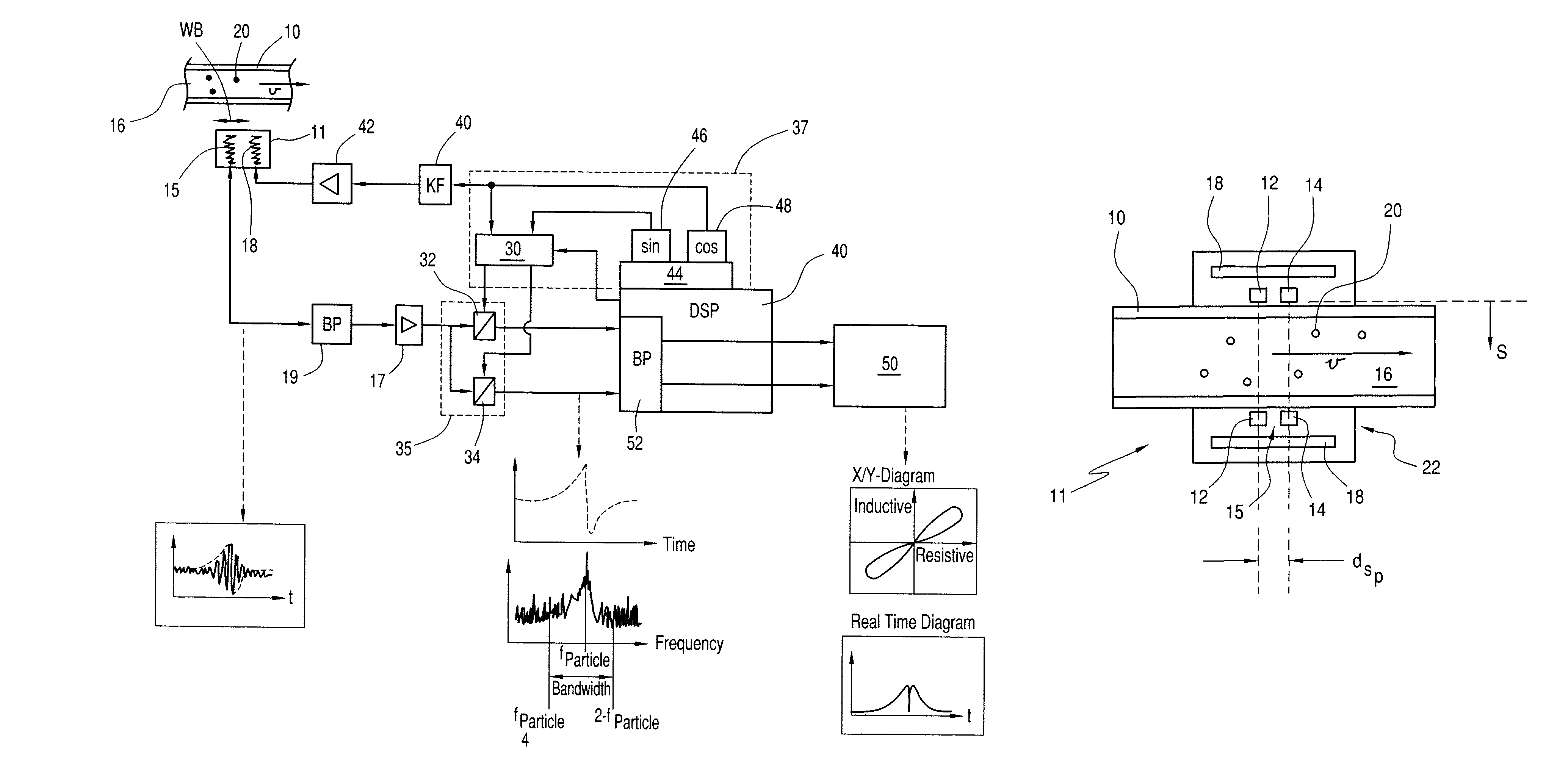
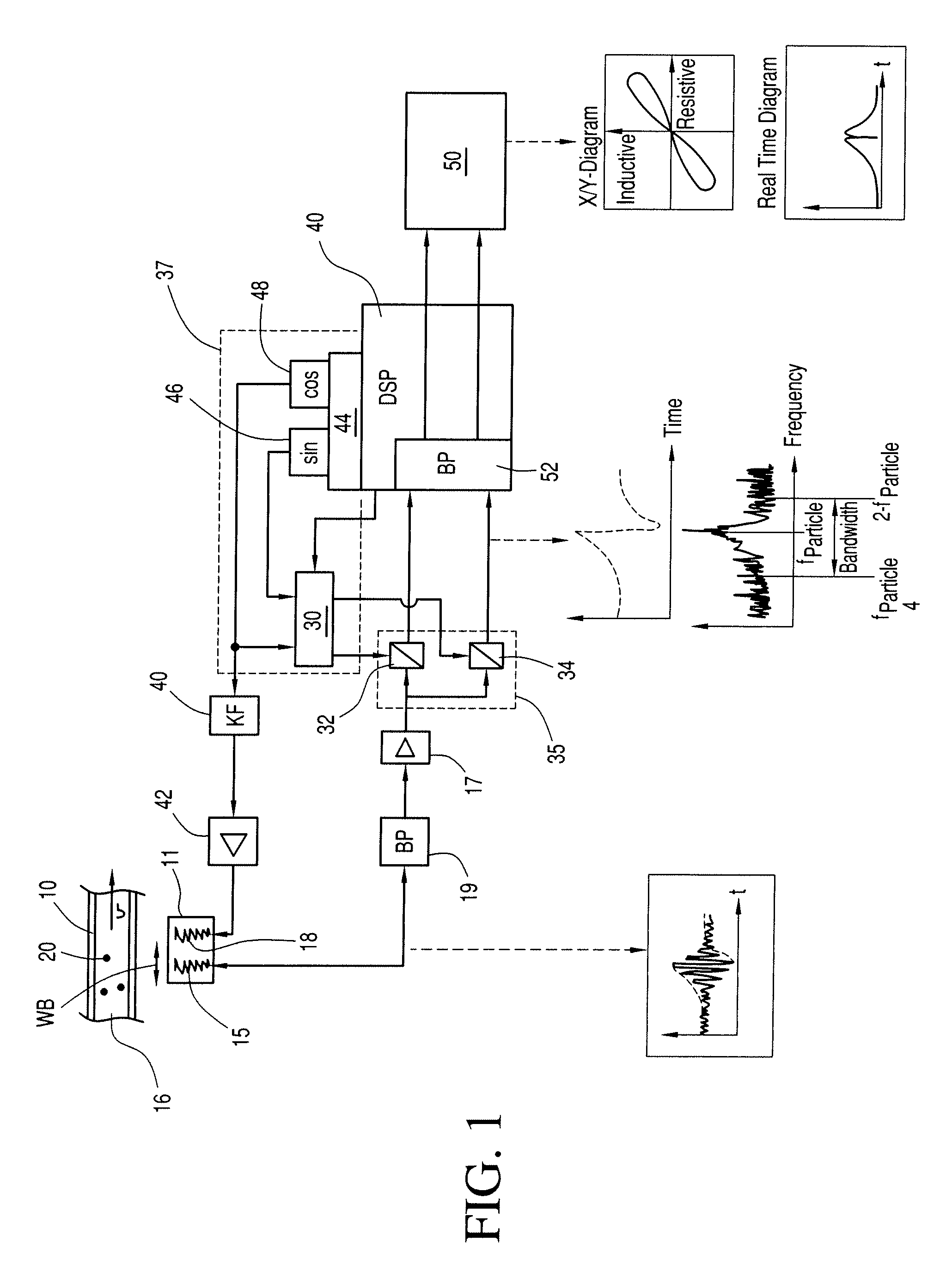
[0050]As shown in FIG. 3, a pipe section 10 is surrounded by a first inductive receiver coil 12 and a second inductive receiver coil 14 located spaced apart from it in the axial direction so that a liquid 16 which is flowing in the pipe section 10 flows through the coils 12 and 14 in the axial direction. The axial distance of the two coils 12, 14 and the axial dimension of the coils 12, 14 can be for example, 2 mm. The two receiver coils 12, 14 are surrounded externally by a transmitter coil 18 which is located coaxially to the two coils 12, 14 and which has a greater diameter than the latter. The axial dimension of the transmitter coil 18 is such that the two receiver coils 12, 14 are located entirely within the transmitter coil 18. Preferably, the extension of the transmitter coil 18 in the axial direction is at least twice as great as the axial extension of the arrangement of the receiver coils 12, 14, i.e., distance plus axial extension of the coils 12, 14. The coils 12, 14, 18 ...


PUM

PropertyMeasurementUnit
transmission frequencyaaaaaaaaaa
sizeaaaaaaaaaa

Abstract

A process and device for detecting electrically conductive particles in a liquid flowing in a pipe section, the liquid being exposed to periodic alternating electromagnetic fields by a transmitter coil which induces eddy currents in the particles, a probe made as a coil arrangement and which has an effective width producing a periodic electrical signal based on the eddy currents. The signal ha a carrier oscillation with an amplitude and / or phase which is modulated by particles passing across the effective width of the coil arrangement, the probe signal being filtered by a frequency-selective first filter unit, the filtered signal being sampled by a triggerable A / D converter stage to obtain a demodulated digital measurement signal, the digital measurement signal being filtered by a digital, frequency-selective adjustable second filter unit to obtain a useful signal, and the useful signal being evaluated to detect passage of electrically conductive particles in the pipe section.

Description

BACKGROUND OF THE INVENTION[0001]1. Field of Invention[0002]The invention relates to a process and a device for detecting electrically conductive particles in a liquid flowing through a pipe by means of eddy currents.[0003]2. Description of Related Art[0004]German Patent Application DE 2 108 717 A1 describes a process and device of the type to which the present invention is directed, two induction coils being located in two branches of an alternating current bridge circuit, the other two branches of which are formed by the halves of another coil. Liquid flows through the coils in the axial direction and the coils can be arranged in succession in the flow direction, the impedance changes which are caused by the passage of the particles and the difference of the impedance change in both coils being evaluated. An arrangement is shown in which the liquid flow is divided into two parallel component sections which each flow through one of the two coils, then an axial offset of the coils i...

Claims


Application Information

Patent Timeline
Patent Type & Authority Patents(United States)
IPC IPC(8): G01N27/74G01N15/06G01R33/12
CPCG01N33/2858G01N15/0656
Inventor BECKER, EDWINKNOELL, THOMASHOELZL, ROLAND
Owner PRUTECHNIK DIETER BUSCH AG
Why Eureka
Try Eureka