Sealed cable and terminal crimp

a terminal crimp and sealing cable technology, applied in the direction of insulated conductors, cables, coupling device connections, etc., can solve the problems of cable corrosion faster, aluminum-based cables crimped to copper alloy or other electrical terminals are also susceptible to galvanic corrosion, and localized pitting and crevice corrosion

a terminal crimp and sealing cable technology, applied in the direction of insulated conductors, cables, coupling device connections, etc., can solve the problems of cable corrosion faster, aluminum-based cables crimped to copper alloy or other electrical terminals are also susceptible to galvanic corrosion, and localized pitting and crevice corrosion

US7960652B2Inactive Publication Date: 2011-06-14APTIV TECH LTD

Image

  • Sealed cable and terminal crimp
  • Sealed cable and terminal crimp
  • Sealed cable and terminal crimp

Examples


Embodiment Construction

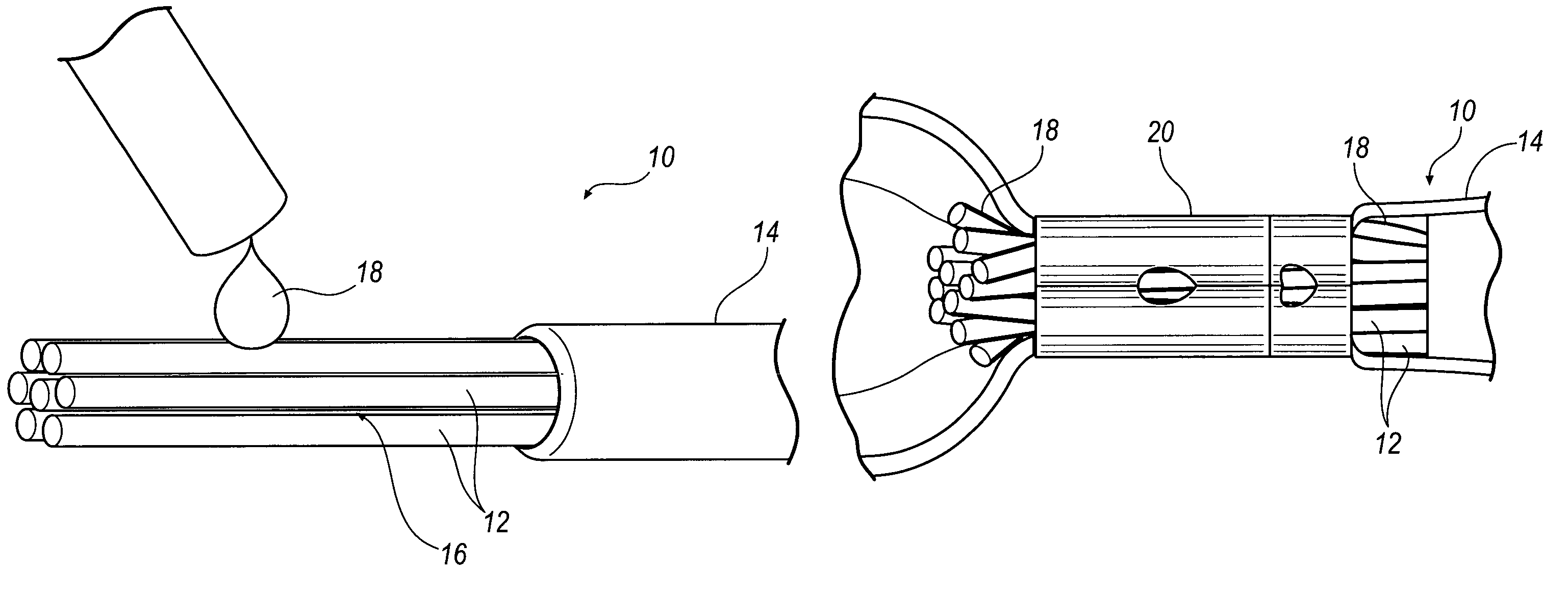
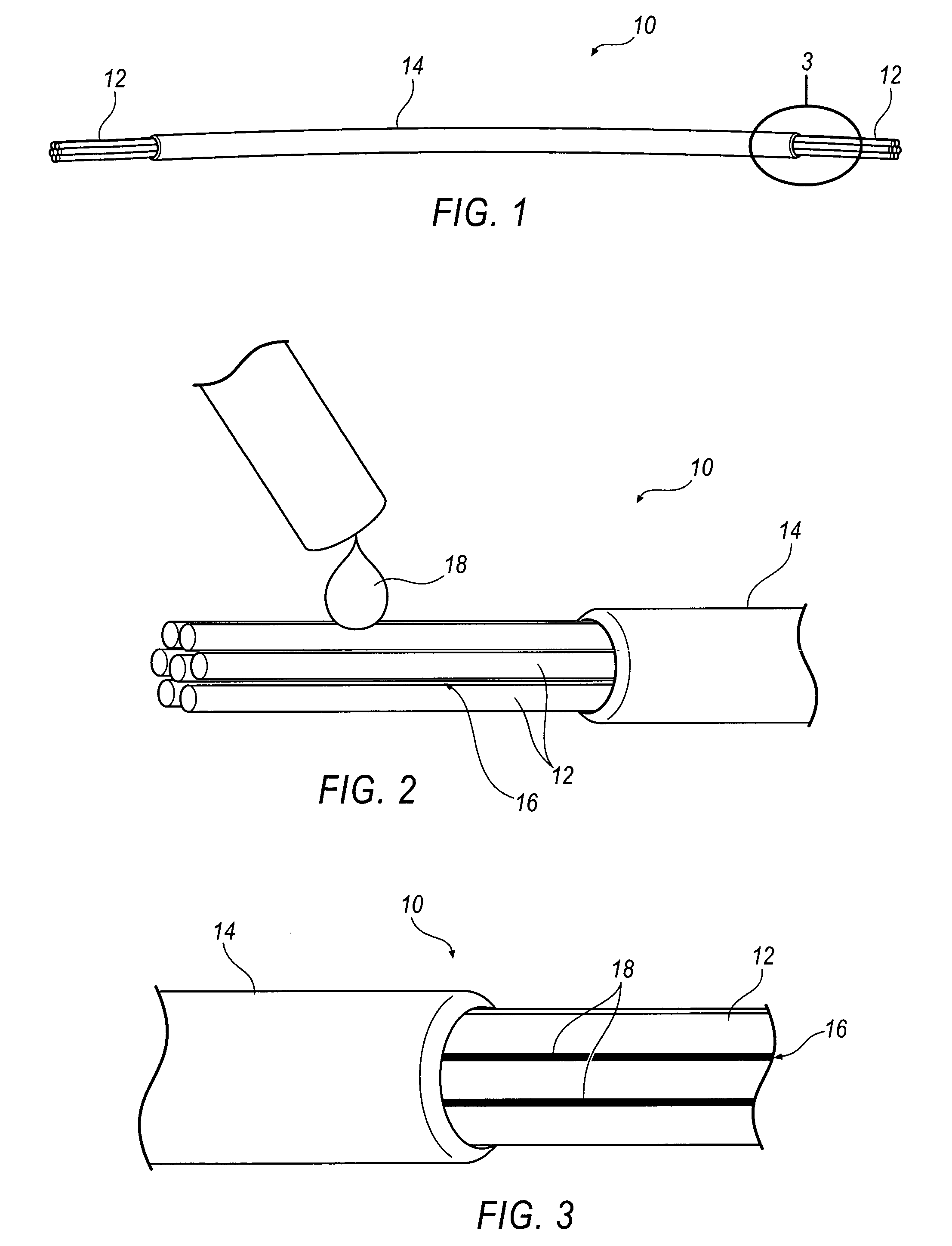
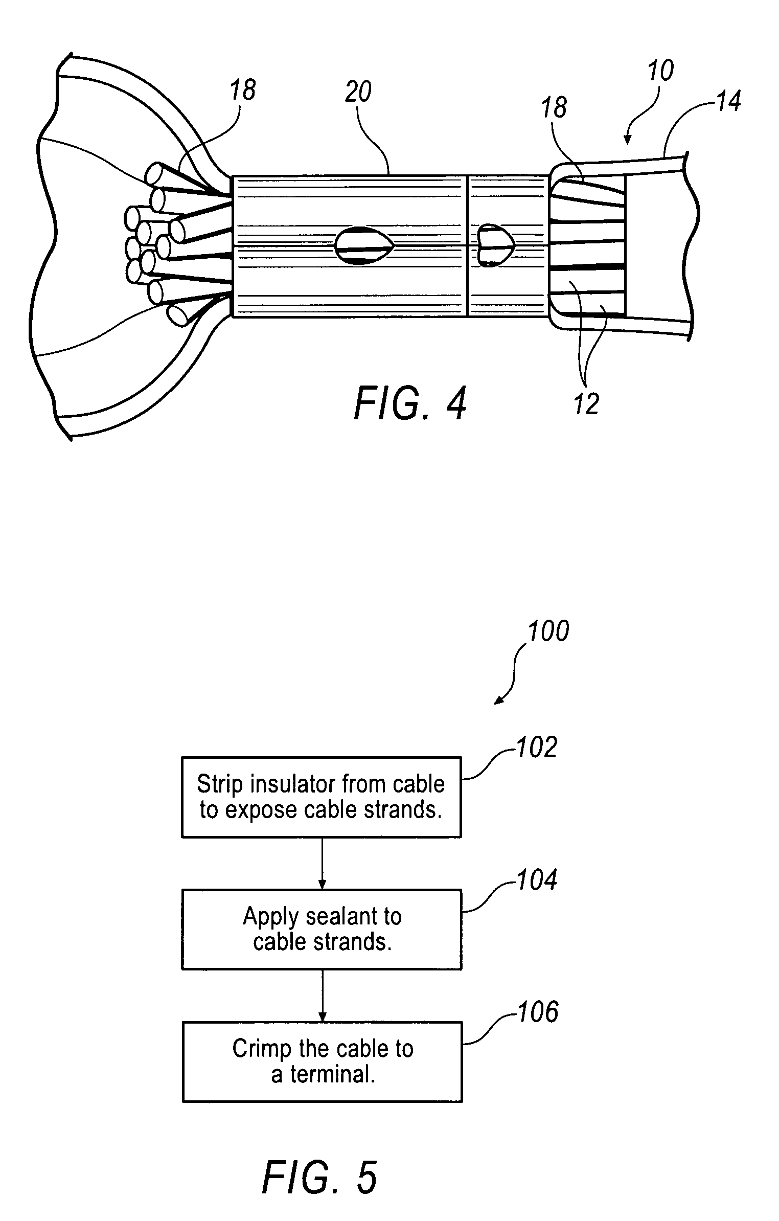
[0011]A cable includes a plurality of cable strands disposed inside an insulator. The insulator is stripped so that the cable strands are at least partially exposed. A sealant is applied to the cable strands, and the sealant is drawn under the insulator and fills in gaps between the cable strands by capillary action. Capillary action is the ability of the cable strands and insulator to wick the sealant from one place to another. Specifically, capillary action may cause the sealant to wick from one end of the cable to another end. Alternatively, capillary action may simply cause the sealant to wick from one end of the cable to at least partially under the insulator. Accordingly, the sealant is able to coat more of the cable strands and further protect the cable strands from corrosion. Additionally, filling the gaps between the cable strands with the sealant prevents the ingress of corrosive liquids.

[0012]FIG. 1 illustrates an exemplary cable 10 that includes a plurality of aluminum-b...


PUM

PropertyMeasurementUnit
lengthaaaaaaaaaa
corrosiveaaaaaaaaaa
conductivityaaaaaaaaaa

Abstract

A cable includes a plurality of cable strands, an insulator disposed on a portion of the plurality of strands such that the plurality of strands are at least partially exposed, and a sealant disposed between gaps of the plurality of strands and at least partially under the insulator. Moreover, a method includes stripping an insulator from an end of the cable to expose a plurality of cable strands, and applying a sealant to the cable strands such that the sealant is drawn under the insulator and fills in gaps between the cable strands by capillary action.

Description

BACKGROUND[0001]Insulated cables are used to provide electrical communication to many devices. Often times, these cables include stranded copper, which has high conductivity, good corrosion resistance, and adequate mechanical strength. However, interest in weight savings and cost savings has increased interest in aluminum-based stranded cable instead of copper. However, aluminum-based cable has different properties, including conductivity, strength, and fatigue life. Perhaps more importantly, copper and aluminum-based cables have different corrosion resistance properties. For example, copper is resistant to salt and other corrosive chemicals while aluminum is resistant to atmospheric corrosion, but is susceptible to localized pitting and crevice corrosion if corrosive liquids enter gaps between the cable strands. Aluminum-based cables crimped to copper alloy or other electrical terminals are also susceptible to galvanic corrosion if an electrolyte is present.[0002]A variety of circu...

Claims


Application Information

Patent Timeline
14 Jun 2011
Publication
US7960652B2
IPC
H02G3/02
CPC
H01R4/183; H01R4/62; H01R13/5205; H01R9/03; Y10T29/53213; H01B7/20; H01B9/04
Inventors
DREW, GEORGE ALBERT; GUMP, BRUCE S.