Optical pH sensor

a technology optical ph sensor, which is applied in the field of optical ph sensor, can solve problems such as advanced deterioration of gathering system

Active Publication Date: 2011-06-14
BOVAIRD
View PDF35 Cites 4 Cited by
  • Summary
  • Abstract
  • Description
  • Claims
  • Application Information

AI Technical Summary

Problems solved by technology

Additionally, pH levels outside certain ranges can cause advanced deterioration of gathering systems.

Method used


Image

  • Optical pH sensor
  • Optical pH sensor
  • Optical pH sensor

Examples


Embodiment Construction

[0021]The embodiments discussed herein are merely illustrative of specific manners in which to make and use the invention and are not to be interpreted as limiting the scope of the instant invention.

[0022]While the invention has been described with a certain degree of particularity, it is to be noted that many modifications may be made in the details of the invention's construction and the arrangement of its components without departing from the spirit and scope of this disclosure. It is understood that the invention is not limited to the embodiments set forth herein for purposes of exemplification.

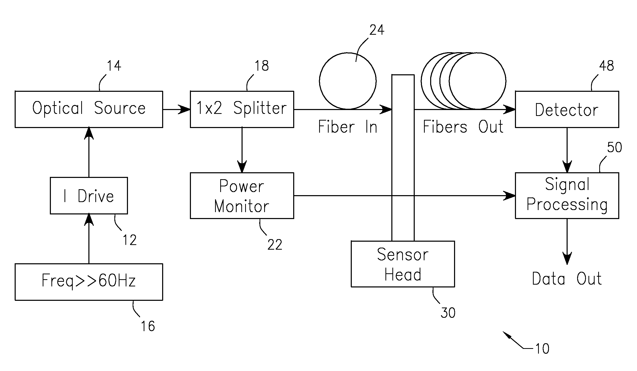
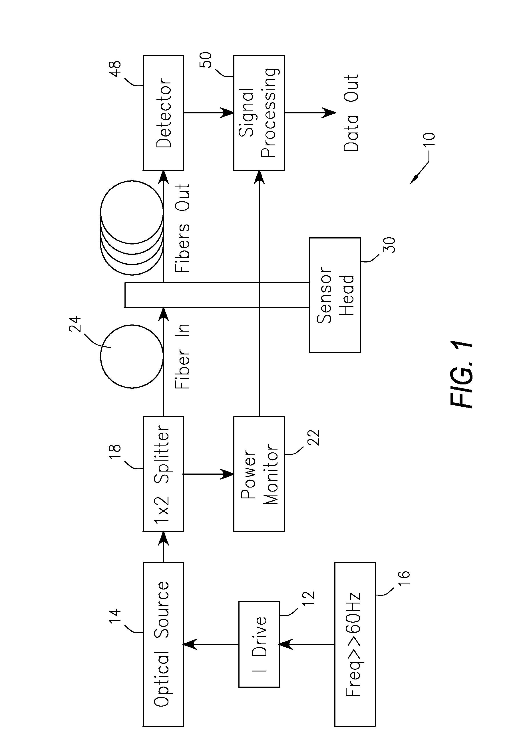
[0023]FIG. 1 illustrates a simplified schematic diagram of a system 10 which includes an optical sensor of the present invention. An electrical current, as shown in box 12, is delivered to an optical source, such as shown at box 14.

[0024]The power to the optical source is modulated by a high frequency, low amplitude alternating current, as shown by box 16. In one embodiment, the optical s...


PUM

PropertyMeasurementUnit
frequenciesaaaaaaaaaa
diameteraaaaaaaaaa
wavelengthaaaaaaaaaa

Abstract

A method to sense pH of a fluid and an optical pH sensor. The method includes the steps of supplying at least a portion of an optical source through an input fiber. The optical source is passed through a sensor head having a sapphire window to a fluid. Optical power reflected from the fluid is collected in a plurality of output fibers in the sensor head. The reflected optical power in the output fibers in the sensor head is thereafter converted to an electrical signal which is used to determine the pH of the fluid.

Description

CROSS-REFERENCE TO PENDING APPLICATIONS[0001]This application is based on and claims priority to U.S. Provisional Patent Application Ser. No. 61 / 142,925, filed Jan. 7, 2009.BACKGROUND OF THE INVENTION[0002]1. Field of the Invention[0003]The present invention relates to an optical sensor for sensing pH of a fluid and to a method to sense the pH of a fluid. In particular, the present invention relates to a method and apparatus for an optical pH sensor which is used with a system for managing liquidation and degradation of organic waste liquids and solids.[0004]2. Prior Art[0005]Various processes and systems have been employed in the past for the liquidation and degradation of organic waste liquids and solids. These may be found in a variety of containers or vessels, such as a grease trap, an interceptor, pulp and paper mills, wastewater, marine and other waste liquid containers. Ideally, a coordinated treatment of waste is employed including the addition of micro-organisms, enzymes, a...

Claims


Application Information

Patent Timeline
Patent Type & Authority Patents(United States)
IPC IPC(8): G01N21/00
CPCG01N21/55G01N21/431
Inventor LOPRESTI, PETERSUBLETTE, KERRY L.ASHENAYI, KAVEHBOVAIRD, BRIAN
Owner BOVAIRD
Why Eureka
Try Eureka