
Surface acoustic wave resonator, and surface acoustic wave filter and antenna duplexer in which the surface acoustic wave resonator is used

a surface acoustic wave and resonator technology, applied in the direction of impedence networks, generators/motors, device material selection, etc., can solve the problems of deterioration unfavorable generation of insertion loss and deteriorated attenuation characteristics, and general disadvantage of surface acoustic filters, so as to improve the leakage of surface acoustic waves and improve the leakage of surface a

Active Publication Date: 2011-06-21
SKYWORKS PANASONIC FILTER SOLUTIONS JAPAN
View PDF17 Cites 17 Cited by
  • Summary
  • Abstract
  • Description
  • Claims
  • Application Information

AI Technical Summary

Benefits of technology

[0009]Therefore, a main object of the present invention is to solve the foregoing problems, and a main object thereof is to provide a surface acoustic wave resonator superior in its characteristics by improving the leak of a surface acoustic wave, and a surface acoustic wave filter and an antenna duplexer in which the surface acoustic wave resonator is used. The present invention relates to a surface acoustic wave resonator comprising a substrate made of lithium niobate, an interdigital transducer electrode provided on an upper surface of the substrate, and a dielectric thin film for covering the interdigital transducer electrode. The interdigital transducer electrode includes bus-bar electrode regions, dummy electrode regions and a finger overlap region, wherein a thickness of the dielectric thin film in upper sections in at least one of the bus-bar electrode regions and the dummy electrode regions is smaller than the thickness of the dielectric thin film above of the finger overlap region. According to the constitution, the leak of the surface acoustic wave in the transverse direction can be effectively improved, and the surface acoustic wave resonator superior in its characteristics can be thereby realized. Further, in the case where the surface acoustic wave resonator is provided in the surface acoustic wave filter and the antenna duplexer, the surface acoustic wave filter and the antenna duplexer can also have superior characteristics.

Problems solved by technology

However, the surface acoustic wave filter, in which the substrate of this type is used, was generally disadvantageous because of its poor temperature characteristic.
However, the conventional surface acoustic wave resonator has a problem that the characteristics thereof are deteriorated by the leak of the surface acoustic wave in the transverse direction resulting from an acoustic velocity in the surface acoustic wave resonator.
Further, in the case where the surface acoustic wave filter comprises the surface acoustic wave resonator, an insertion loss and a deteriorated attenuation characteristic are unfavorably generated in the surface acoustic wave filter.[Patent Document 1] Unexamined Japanese Patent Publication No. 2003-209458.

Method used


Image

  • Surface acoustic wave resonator, and surface acoustic wave filter and antenna duplexer in which the surface acoustic wave resonator is used
  • Surface acoustic wave resonator, and surface acoustic wave filter and antenna duplexer in which the surface acoustic wave resonator is used
  • Surface acoustic wave resonator, and surface acoustic wave filter and antenna duplexer in which the surface acoustic wave resonator is used

Examples


embodiment 1

Preferred Embodiment 1

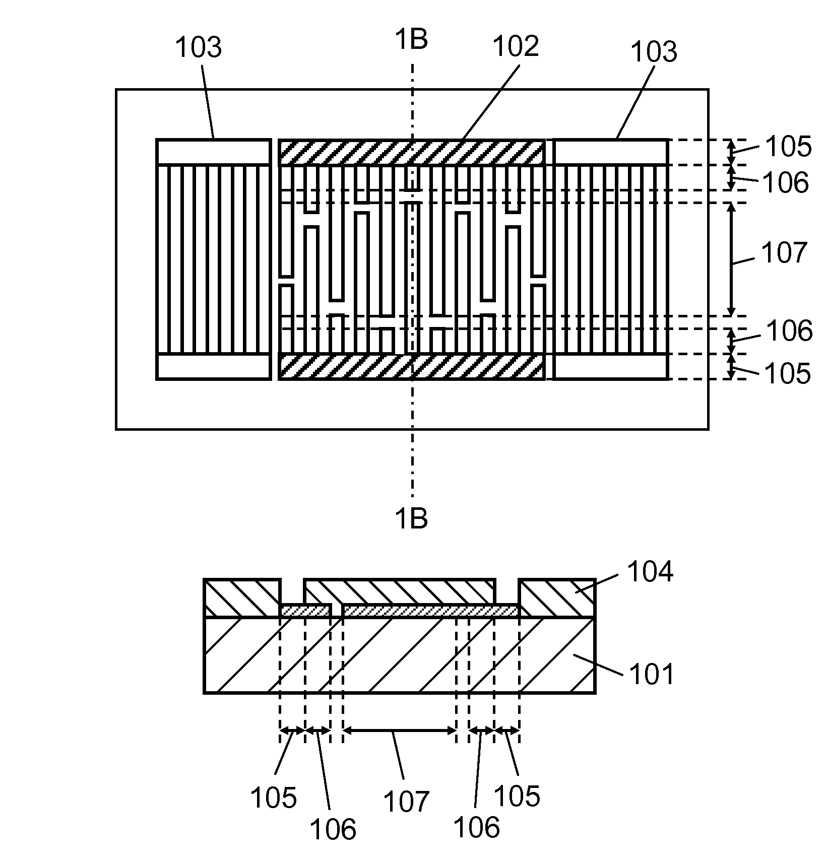
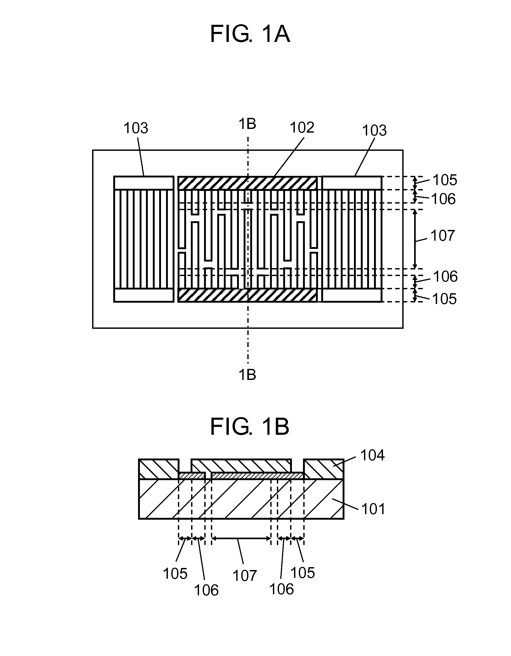
[0037]FIG. 1A is a top view showing a constitution of a surface acoustic wave resonator according to a preferred embodiment 1 of the present invention. FIG. 1B is a sectional view of 1B-1B shown in FIG. 1A. Interdigital transducer electrode 102 and reflector electrodes 103 are formed on piezoelectric substrate 101, and SiO2 thin film 104 is further formed thereon. Interdigital transducer electrode 102 includes bus-bar electrode regions 105, dummy electrode regions 106 and finger overlap region 107. Interdigital transducer electrode 102 is apodization-weighted in order to control the spurious in the transverse mode. Dummy electrode region 106 denotes a region representing a minimum length of a dummy electrode in interdigital transducer electrode 102, while finger overlap region 107 denotes a region representing a crossover maximum length in interdigital transducer electrode 102. Further, SiO2 thin film 104 is removed so that the electrodes are exposed in upper s...

embodiment 2

Preferred Embodiment 2

[0052]FIG. 6A is a top view showing a constitution of a surface acoustic wave resonator according to a preferred embodiment 2 of the present invention. FIG. 6B is a sectional view of 6B-6B shown in FIG. 6A. Interdigital transducer electrode 702 and reflector electrodes 703 are formed on piezoelectric substrate 701, and SiO2 thin film 704 is further formed thereon. Interdigital transducer electrode 702 includes bus-bar electrode regions 705, dummy electrode regions 706 and finger overlap region 707, wherein the interdigital transducer electrode of the normal type, which is not subjected to the apodized-weighting, is adopted. Dummy electrode region 706 denotes a region representing a minimum length of the dummy electrode in interdigital transducer electrode 702, while finger overlap region 707 denotes region representing a crossover maximum length of the interdigital transducer electrode. To dummy electrode region 706 is applied dummy electrode weighing 708 which...

embodiment 3

Preferred Embodiment 3

[0069]FIG. 10 shows a constitution of a surface acoustic wave filter according to a preferred embodiment 3 of the present invention. Referring to reference symbols shown in FIG. 10, 1101, 1102, 1103 and 1104 denote serial-arm surface acoustic wave resonators, while 1105 and 1106 denote parallel-arm surface acoustic wave resonators. As the surface acoustic wave resonators 1101, 1102, 1103, 1104, 1105 and 1106, the surface acoustic wave resonator shown in the preferred embodiment 1 or 2 is used. Thus, the surface acoustic wave filter of the ladder type having superior characteristics can be realized.

[0070]In the present preferred embodiment, the surface acoustic wave filter of the ladder type comprising the six surface acoustic wave resonators 1101, 1102, 1103, 1104, 1105 and 1106 is described. However, the number of the surface acoustic wave resonators to be provided and the constitution of the filter are not limited thereto. As far as the surface acoustic wave ...


PUM


Abstract

The present invention provides a surface acoustic wave resonator capable of improving a leak of a surface acoustic wave in the transverse direction and reducing the spurious and having superior characteristics. In a surface acoustic wave filter according to the present invention, an interdigital transducer electrode and reflector electrodes are formed on a piezoelectric substrate, and a SiO2 thin film is formed on at least a portion of the interdigital transducer electrode. The interdigital transducer electrode includes a bus-bar electrode region, a dummy electrode region and a finger overlap region, such that the SiO2 thin film is removed from upper sections of the bus-bar electrode regions of the interdigital transducer electrode.

Description

[0001]This application is a U.S. national phase application of PCT International Application PCT / JP2007 / 074084, filed Dec. 14, 2007BACKGROUND OF THE INVENTION[0002]1. Field of the Invention[0003]The present invention relates to a surface acoustic wave resonator, and a surface acoustic wave filter and an antenna duplexer in which the surface acoustic wave resonator is used.[0004]2. Background of the Invention[0005]In order to realize a surface acoustic wave filter advantageously characterized in its broadband, a piezoelectric substrate having a large electromechanical coupling coefficient, such as a lithium niobate substrate (LiNbO3), was conventionally used. However, the surface acoustic wave filter, in which the substrate of this type is used, was generally disadvantageous because of its poor temperature characteristic. In order to improve the temperature characteristic, there is a proposed constitution wherein a SiO2 thin film layer is formed on the LiNbO3 substrate, and a value o...

Claims


Application Information

Patent Timeline
Patent Type & Authority Patents(United States)
IPC IPC(8): H03H9/64H03H9/72H01L41/09H01L41/18H01L41/22H01L41/23H01L41/29H03H9/145H03H9/25
CPCH03H9/02858H03H9/1452H03H9/02992H03H9/02881H03H3/08H03H9/25
Inventor NAKAMURA, HIROYUKINAKANISHI, HIDEKAZUIWASAKI, YUKIOMATSUNAMI, KENTSURUNARI, TETSUYA
Owner SKYWORKS PANASONIC FILTER SOLUTIONS JAPAN
Learn More