Line resonance analysis system

a resonance analysis and line resonance technology, applied in electrical testing, instruments, electric digital data processing, etc., can solve the problems of limiting the sensitivity of such methods and unable to achieve global cable condition assessmen

Active Publication Date: 2011-06-21
WIRESCAN
View PDF5 Cites 26 Cited by
  • Summary
  • Abstract
  • Description
  • Claims
  • Application Information

AI Technical Summary

Benefits of technology

[0019]The object of the invention is to solve or at least alleviate the problems indicated above. To reduce background noise and increase sensitivity, the invention goes through a transformation into the domain of the line impedance (both amplitude and phase), also called the domain of t′, and applies frequency analysis in this domain. The steps involved in this process are:
[0039]LIRA (Line Resonance Analysis System) improves the detection sensitivity and accuracy by analyzing the cable input impedance (equation (8) and FIG. 1). In essence, the following steps are provided:

Problems solved by technology

However, if the line length is higher than the signal wavelength, (L≧λ), the line characteristics take an important role and the circuit impedance seen from the generator does not match the load, except for some very particular cases.
Line attenuation and environment noise in real environments limit the sensitivity of such methods, preventing the possibility to detect degradations at an early stage, especially for cables longer than a few kilometers.
In addition, no global cable condition assessment is possible, which is important for cable residual life estimation in harsh environment applications (for example nuclear and aerospace applications).

Method used


Image

  • Line resonance analysis system
  • Line resonance analysis system
  • Line resonance analysis system

Examples


Embodiment Construction

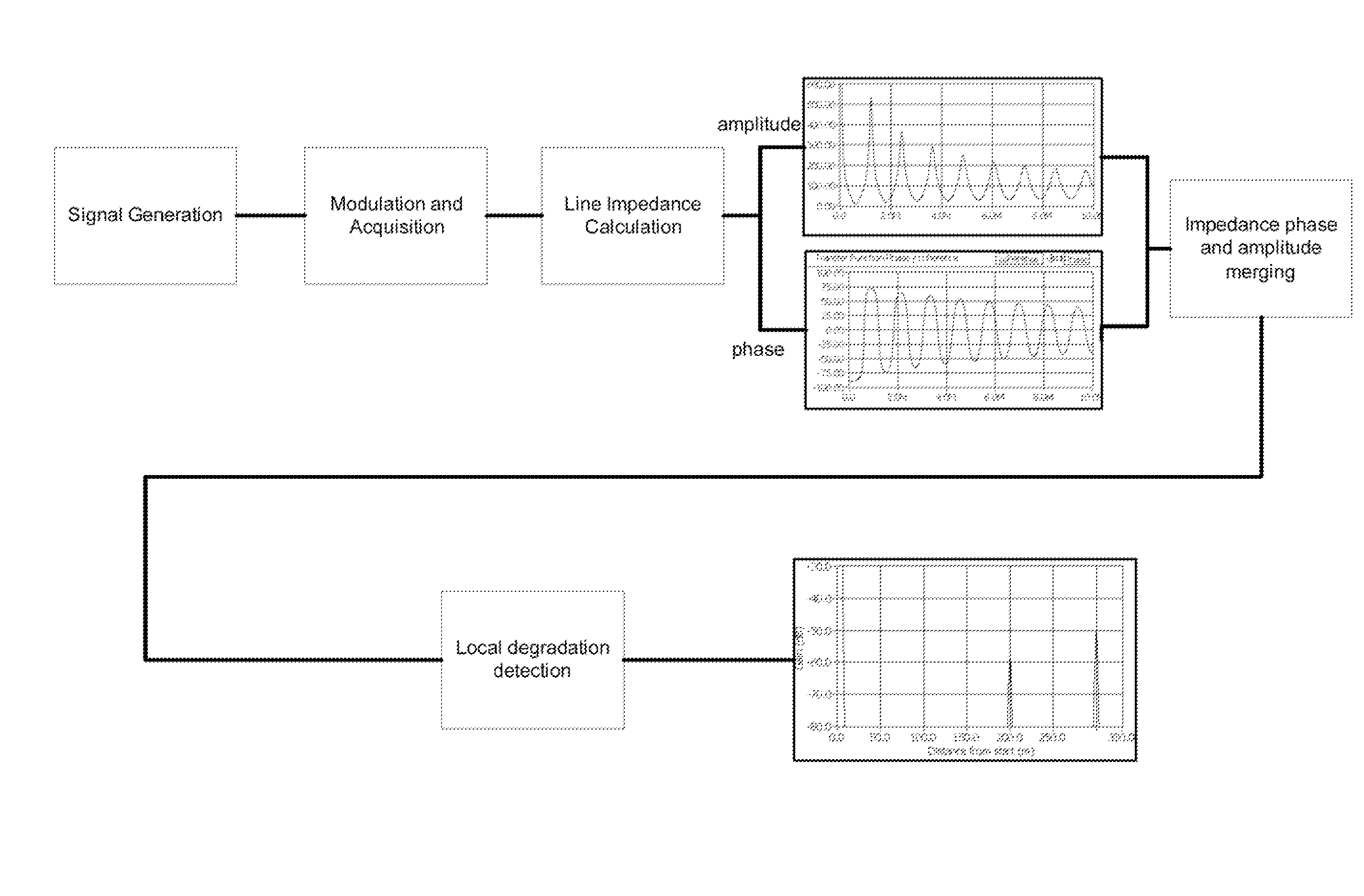
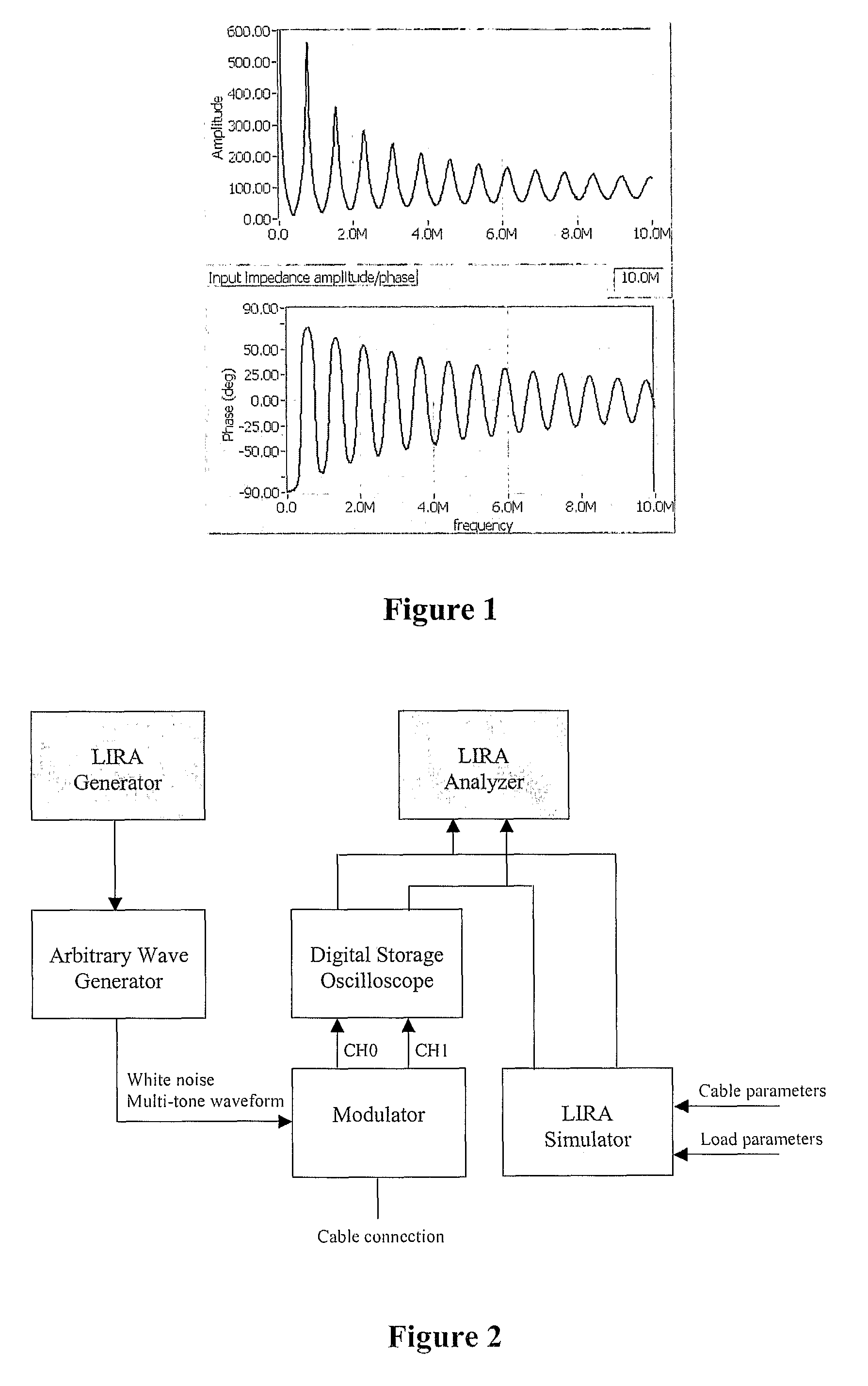
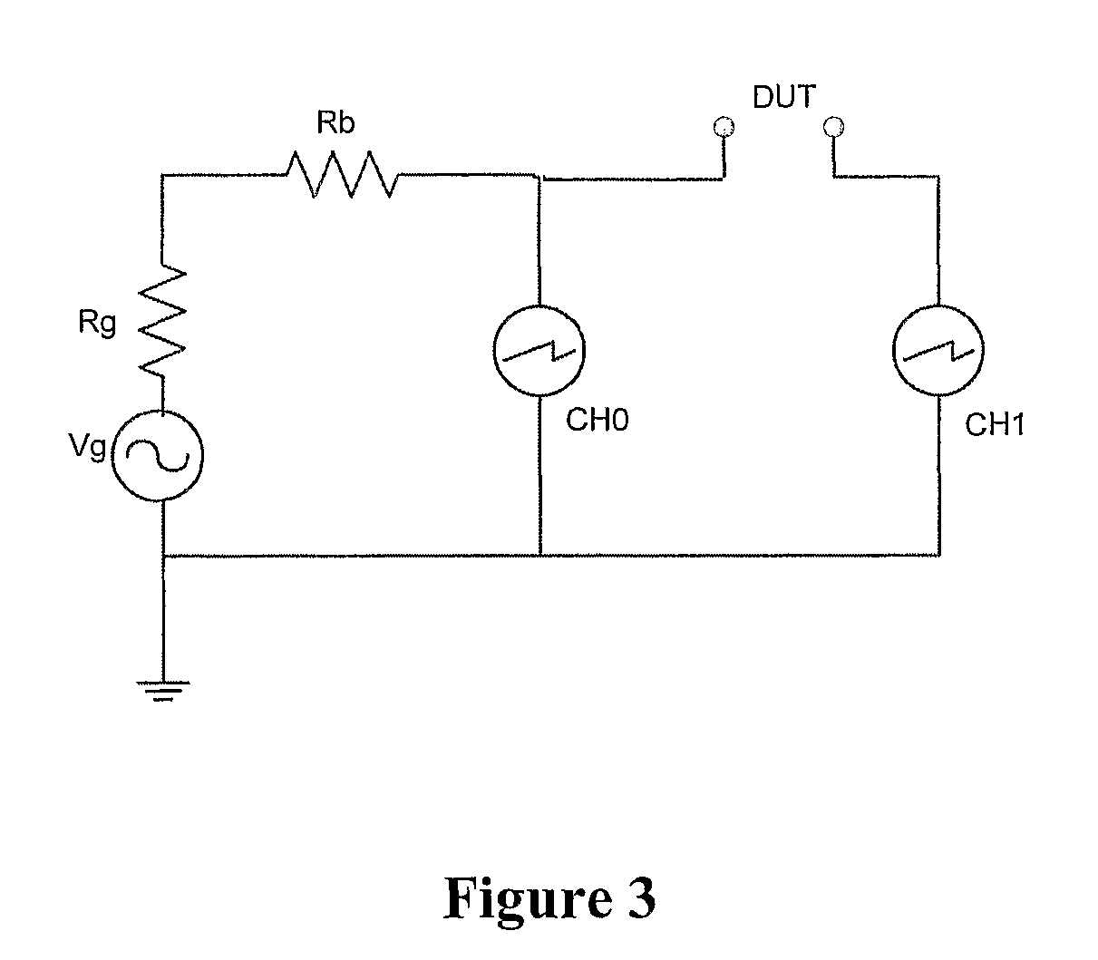
[0060]FIG. 2 shows an embodiment of the system with hardware and software modules. These modules will be described below.[0061]The Arbitrary Wave Generator. It is driven by the LIRA Generator software to supply the system with a reference signal CH0. The reference signal can be:[0062]A white noise signal.[0063]A sweep signal, from 0 Hz to the selected bandwidth. Same effect as of a white noise signal.[0064]A multi-tone sine wave. This is used for real-time monitoring of impedance phase shifts.[0065]The Modulator. A functional diagram of the modulator is shown in FIG. 4. The output of this module is the reference signal (CH0), distorted by the generator internal impedance Rg, and a phase and amplitude modulated signal (CH1), which is modulated by the frequency dependent impedance ZDUT of the cable provided to the modulator through a cable connection.[0066]The modulator functional diagram is shown in FIG. 4, where DUT is the connection to the cable under test. The impedance at DUT is ...


PUM


Abstract

The present invention provides a method for monitoring a condition of an electrical cable, the method including: providing a reference signal CH0 and a signal CH1, the signal CH1 being the reference signal CH0 after amplitude and phase modulation by a cable impedance ZDUT of the electrical cable; calculating the cable impedance ZDUT as a function of the applied signal frequency based on the reference signal CH0 and the signal CH1; and analyzing the cable impedance providing an assessment of the cable condition. A system performing the method is also disclosed.

Description

[0001]This application claims priority to U.S. Provisional Application No. 60 / 722,450 filed Oct. 3, 2005, the subject matter thereof incorporated herein by reference.INTRODUCTION[0002]The present invention provides a system and a method for monitoring of installed electrical cables based on line resonance analysis. For example, monitoring includes condition monitoring and real-time diagnosis of the electric cables. Throughout the present description the system is also referred to as LIRA (Line Resonance Analysis System). The cables have lengths ranging from a few meters to several hundred kilometers, depending on the cable structure and attenuation.BACKGROUND[0003]LIRA (Line Resonance Analysis System) is based on transmission line theory, an established and well documented theory that is at the base of two other existing cable fail detection techniques known as “Time Domain Reflectometry” (TDR) and “Frequency Domain Reflectometry” (FDR). Differences and limitations of these two exis...

Claims


Application Information

Patent Timeline
Patent Type & Authority Patents(United States)
IPC IPC(8): G01R31/08
CPCG01R31/021G01R27/04G01R31/11G01R31/58G01R31/08
Inventor FANTONI, PAOLO F.
Owner WIRESCAN
Why Eureka
Try Eureka