
Method for analyzing operation of a machine

a technology of operation and machine, applied in the direction of instruments, testing/monitoring control systems, nuclear elements, etc., can solve the problems of machine idleness, machine “starvation”, and downtime, and achieve the effect of facilitating the prediction of the future operation of each machin

Inactive Publication Date: 2011-06-21
FORD MOTOR CO
View PDF0 Cites 5 Cited by
  • Summary
  • Abstract
  • Description
  • Claims
  • Application Information

AI Technical Summary

Benefits of technology

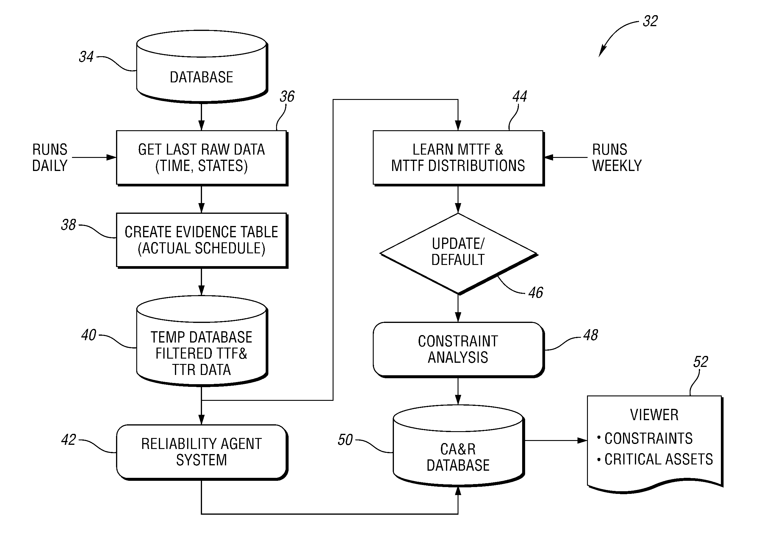
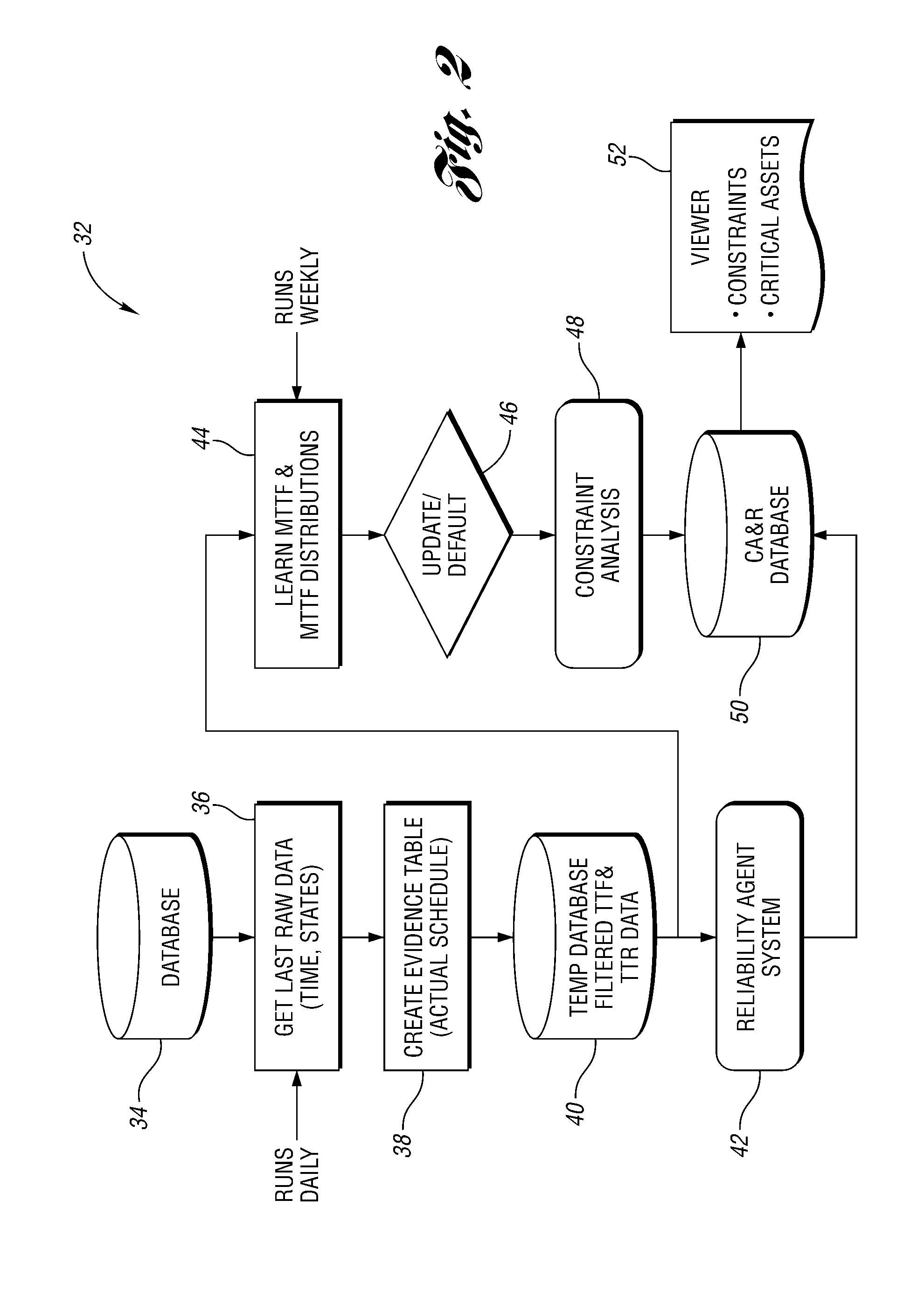
[0016]With regard to the first of these features—i.e., automatic filtering of outliers and inferring plant schedule based on the state of the assets—the present invention can perform a number of steps to increase the accuracy of the information generated for machine reliability and constraint analysis. For example, a conventional FIS assumes that an accurate and regularly updated schedule of plant operation is available. In reality, this assumption is not always true, especially in cases when unscheduled breaks and outages occur, or the person responsible for updating the schedule is not available. In order to avoid inaccuracies, the present invention provides a method for continuously analyzing the state of the individual assets, and infers the actual schedule based on the actual data reported by the base FIS.
[0049]The invention also provides a method for analyzing operation of a plurality of machines. The method includes collecting operation data for each of the machines over a plurality of predetermined time periods. The operation data for each machine includes the respective time for a plurality of events that together form a set of mutually exclusive events that describe operation of the respective machine. For each of the predetermined time periods it is determined whether each machine is in an ON state or an OFF state based at least in part on the collected operation data for the respective machine. Data for the OFF states is removed from at least a portion of the collected operation data, thereby generating a filtered data set. Reliability information is generated for each machine based at least in part on the filtered data set. This facilitates predictions of the future operation of each machine. The reliability information can then be used to perform a constraint analysis for the machines.

Problems solved by technology

Conversely, a “blocked time” is a time during which the machine is forced to be idle because the next machine in the work cell or line is not ready to receive another part.
A similar situation occurs when the prior machine in the work cell or line has not finished its operations, and therefore has no parts to transfer to the machine under analysis: in such a case, the machine is “starved”.
“Downtime” can occur for any number of reasons, including tool breakage, machine failure, etc.
Despite providing some benefits over manual data collection, conventional FIS's are passive systems that produce predefined reports, and have limited analytical, modeling, and prognostic capability.

Method used


Image

  • Method for analyzing operation of a machine
  • Method for analyzing operation of a machine
  • Method for analyzing operation of a machine

Examples


Embodiment Construction

)

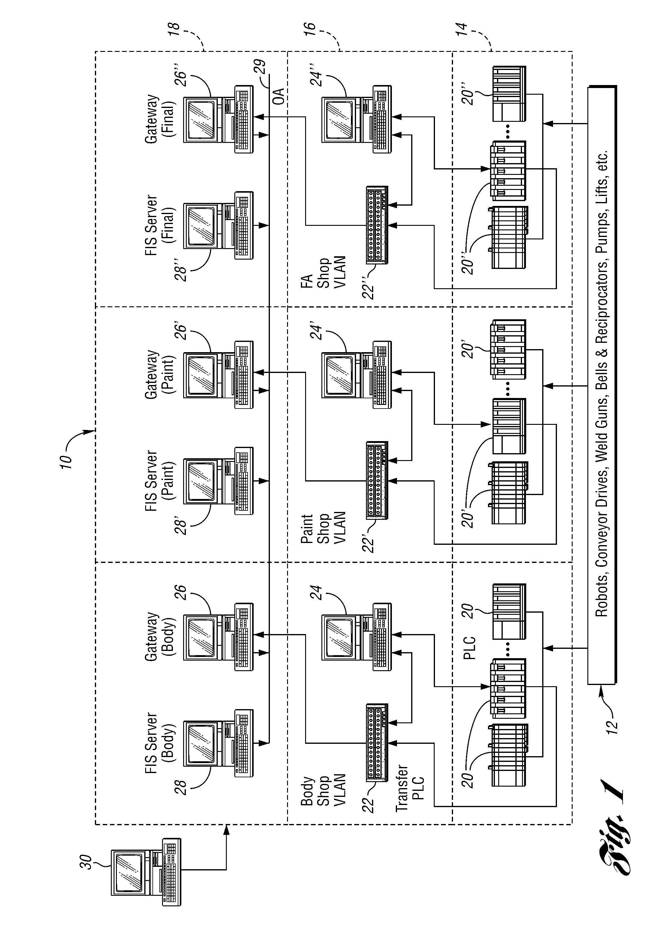
[0059]FIG. 1 shows a schematic representation of a factory information system (FIS) 10 in communication with a number of manufacturing assets 12, such as robots, conveyor drives, weld guns, etc. The FIS 10 is a three-layer system with the first layer 14 including a number of PLC's 20, 20′, 20″. As shown in FIG. 1, the PLC's 20 are used to control manufacturing assets in a body shop. Similarly, the PLC's 20′ are used to control assets used in a paint shop, and the PLC's 20″ are used to control assets used in a final assembly (FA) shop. The same nomenclature using the prime and double prime symbols is used throughout the description of the FIS 10 to indicate similar components used in the different manufacturing areas.

[0060]The FIS 10 also includes an intermediate layer 16 of transfer PLC's 22, 22′, 22″, each of which is connected to a respective personal computer 24, 24′, 24″. Each of the computers 24, 24′, 24″ is in communication with a respective one of the asset controlling PLC's...


PUM


Abstract

A constraint analysis and reliability agent executes a method for analyzing operation of a manufacturing asset, and includes the steps of collecting operation data for a machine over a plurality of predetermined time periods. The operation data includes a plurality of mutually exclusive events that describe operation of the machine. For each of the predetermined time periods, it is determined whether the machine is in an “ON” or an “OFF” state. Data for the “OFF” states is removed from the collected data to generate a filtered data set. Reliability information is then generated based, at least in part, on the filtered data set. This facilitates predictions of future machine operation.

Description

BACKGROUND OF THE INVENTION[0001]1. Field of the Invention[0002]The present invention relates to a method for analyzing operation of a machine, and in particular, a method of reliability and constraint analysis for a machine.[0003]2. Background Art[0004]Recently, Factory Information Systems (FIS's) have become an important tool in automotive manufacturing. They can provide important information about the operation of various “assets”, such as robots, conveyor drives, weld guns, pumps, or other equipment used in manufacturing. A typical automotive FIS is based on a three layer information architecture, including a lower layer of asset controlling programmable logic controllers (PLC's), an intermediate layer of transfer PLC's, and a layer of servers that are accessible from an office automation (OA) network. Each of the asset controlling PLC's sends to a respective one of the transfer PLC's a standard package of data blocks. These data blocks can include, for example, data related to ...

Claims


Application Information

Patent Timeline
Patent Type & Authority Patents(United States)
IPC IPC(8): G06F17/00
CPCG05B23/0283G05B23/0221
Inventor FILEV, DIMITARCOFFMAN, JR., PAUL E.TSENG, FLING
Owner FORD MOTOR CO
Learn More