Mounting and cooling device for emissions system electronics

a cooling device and electronics technology, applied in the direction of power cables, cables, lighting and heating apparatus, etc., can solve the problems of difficult access to the basic housing of the '712 system, difficulty in mounting and interconnecting exhaust treatment components, and '712 system being bulky and lacking flexibility

Active Publication Date: 2011-06-28
CATERPILLAR INC
View PDF23 Cites 36 Cited by
  • Summary
  • Abstract
  • Description
  • Claims
  • Application Information

AI Technical Summary

Problems solved by technology

However, due to the increasing complexity and number of exhaust treatment components and the small amount of available space, mounting and interconnecting exhaust treatment components has proven difficult.
Although the system of the '712 publication may have a detachable add-on housing, the '712 system may still be bulky and lack flexibility.
Furthermore, accessing and maintaining the basic housing of the '712 system may be difficult.
Additionally, locating several exhaust devices in a housing can create extremely high temperatures.
The '712 system does not provide a method for cooling any electronics that may be associated with the '712 system, which could potentially lead to overheating and failure of the electronics.

Method used


Image

  • Mounting and cooling device for emissions system electronics
  • Mounting and cooling device for emissions system electronics
  • Mounting and cooling device for emissions system electronics

Examples


Embodiment Construction

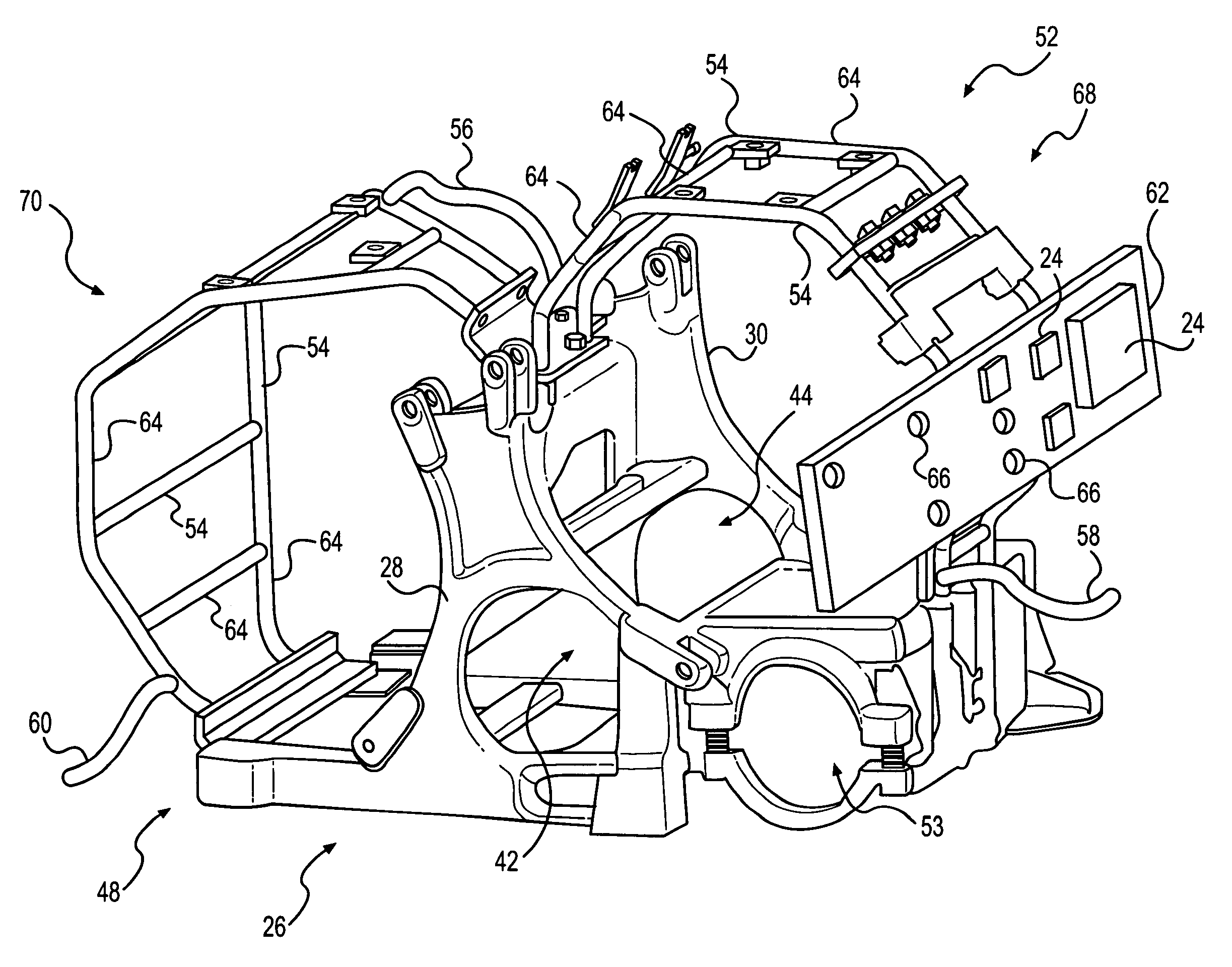
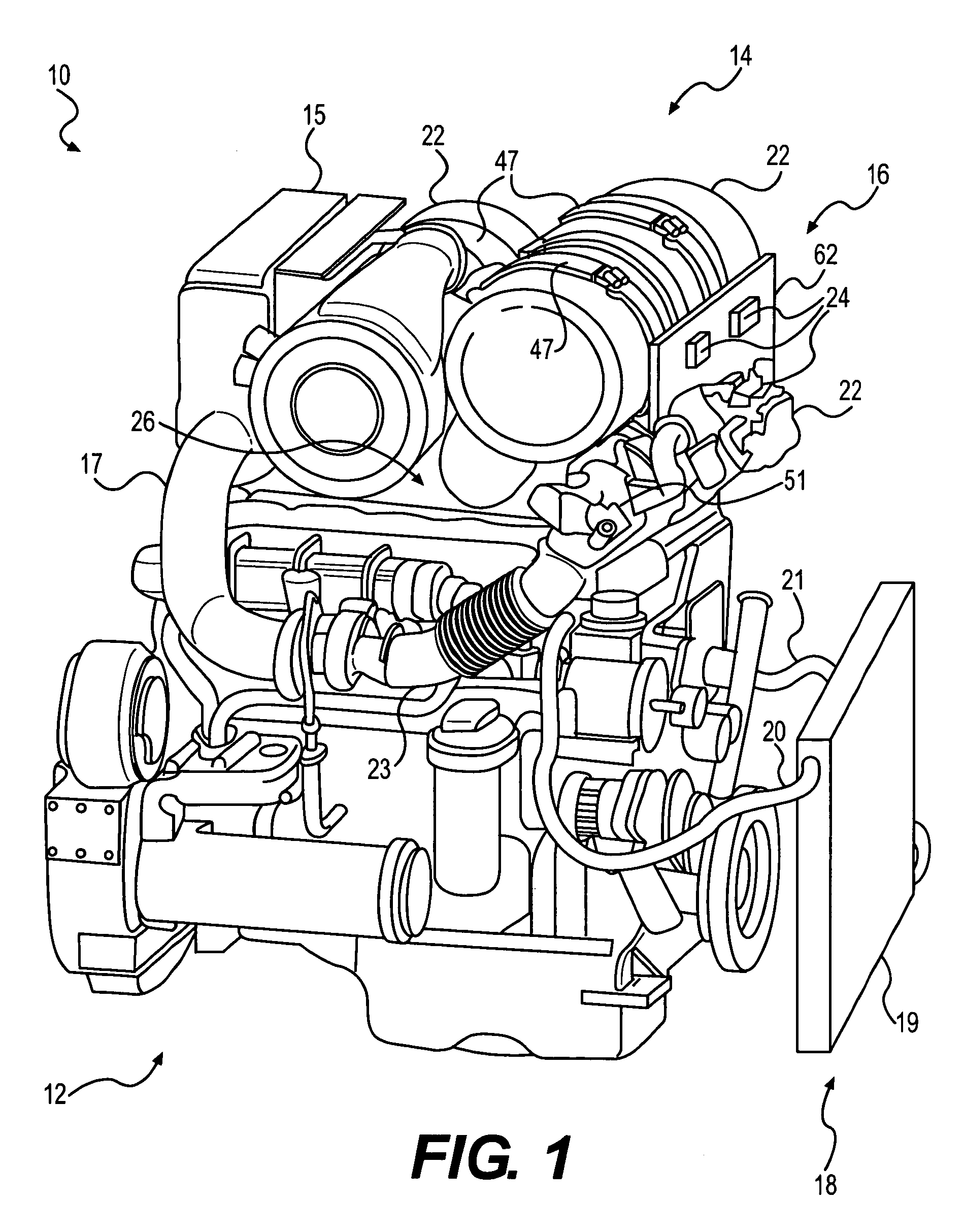
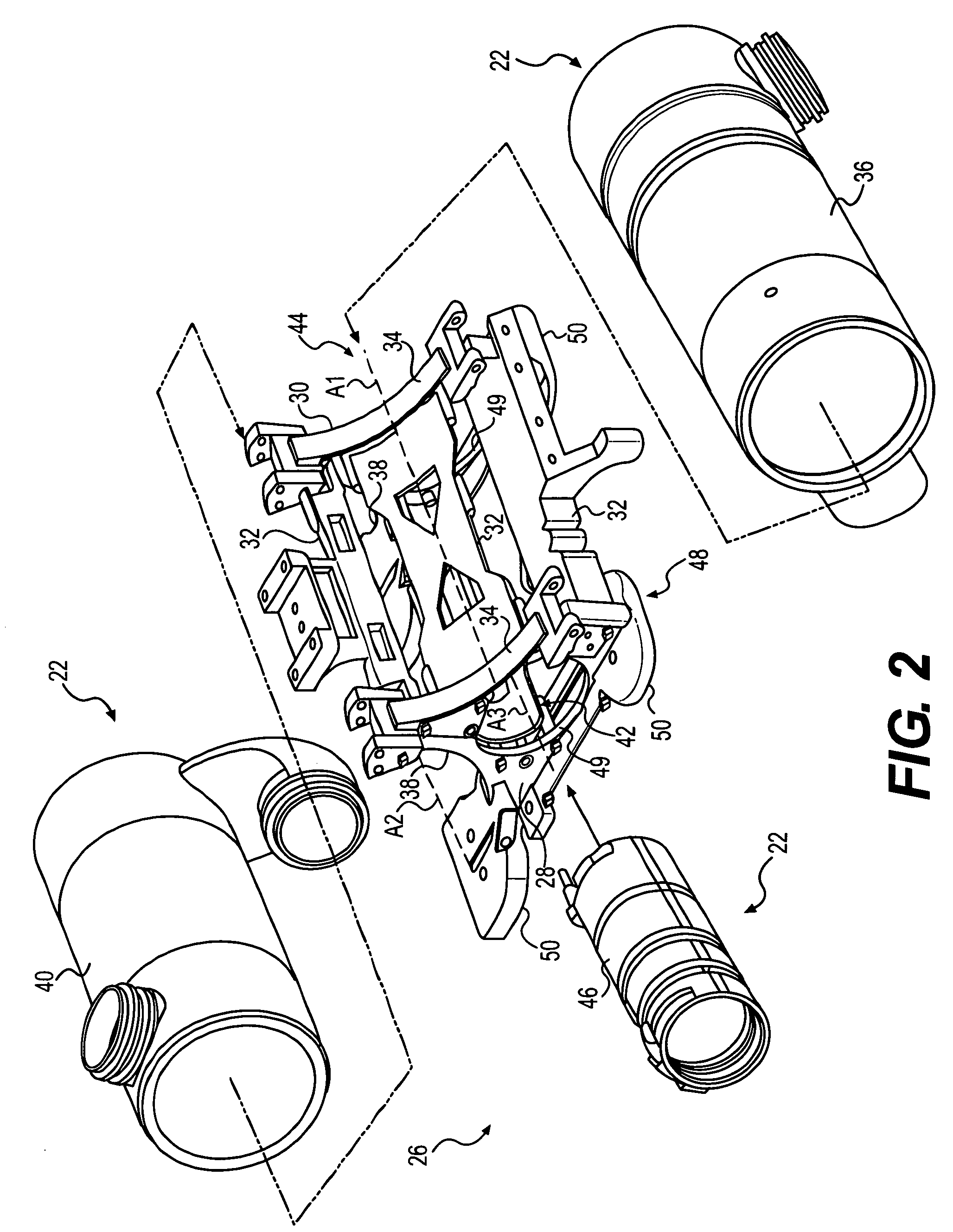
[0016]FIG. 1 illustrates a diagrammatic representation of a power system 10, which may include a power source 12 and an exhaust system 14. Power source 12 may embody a combustion engine, such as, for example, a diesel engine, a gasoline engine, a gaseous fuel-powered engine (e.g., a natural gas engine), or any other type of combustion engine known to one skilled in the art. Power source 12 may have a plurality of combustion chambers (not shown) that convert potential chemical energy (usually in the form of a combustible gas) into useful mechanical work. It is also considered that power source 12 may embody a furnace or a similar device. Power source 12 may receive air from an air cleaner 15 which fluidly communicates with power source 12 via intake 17. Power source 12 may output a flow of exhaust via an exhaust conduit 23.

[0017]Power source 12 may include a cooling system 18 to dissipate heat from power source 12 and / or other components associated with power system 10. Cooling syste...


PUM


Abstract

A cooling device for emissions system electronics is disclosed. The cooling device may have a mount for an exhaust treatment device. The mount may have a framework comprising a plurality of rigid members. The cooling device may also have a passageway located within at least one rigid member of the plurality of rigid members. The passageway may be configured to transmit a flow of coolant. The cooling device may further have a plate coupled to the at least one rigid member and at least one electronic device coupled to the plate. The at least one electronic device may be associated with the exhaust treatment device.

Description

TECHNICAL FIELD[0001]The present disclosure relates generally to a mounting device for emissions system components and, more particularly, to a mounting and cooling device for emissions system electronics.BACKGROUND[0002]Conventional diesel powered systems for engines, factories, and power plants produce emissions that contain a variety of pollutants. These pollutants may include, for example, particulate matter (e.g., soot), nitrogen oxides (NOx), and sulfur compounds. Due to heightened environmental concerns, engine exhaust emission standards have become increasingly stringent. In order to comply with emission standards, machine manufacturers have developed and implemented a variety of exhaust treatment components to reduce pollutants in exhaust gas prior to the exhaust gas being released into the atmosphere. The exhaust treatment components may include, for example, a diesel particulate filter, a selective catalytic reduction device, a diesel oxidation catalyst, a fuel-fired burn...

Claims


Application Information

Patent Timeline
Patent Type & Authority Patents(United States)
IPC IPC(8): F01P1/06F01N3/00F16M11/00H05K7/20F28F7/00
CPCF01N13/00
Inventor OLSEN, PAUL FREDERICKMERCHANT, JACK ALBERTCHARLES, ERIC JAMESTRICHIRAPALLI, MUTHUKUMAR CHANDRASEKARAN
Owner CATERPILLAR INC
Why Eureka
Try Eureka