Radially energized oil capture device for a geared turbofan

a geared turbofan and oil capture technology, which is applied in the direction of liquid fuel engines, machines/engines, mechanical equipment, etc., can solve the problems of additional management of leakage oil, inability to obtain sufficient secondary air pressurization, and inability to utilize the scupper system with the rear bearing compartment, etc., to reduce the possibility of leakage oil

Active Publication Date: 2011-06-28
RTX CORP
View PDF4 Cites 15 Cited by
  • Summary
  • Abstract
  • Description
  • Claims
  • Application Information

AI Technical Summary

Benefits of technology

[0006]A turbine engine has a bearing seal located between a rear bearing compartment and an air compartment to seal oil within the rear bearing compartment and pressurized air in the air compartment. A plurality of knife edge seals are used to meter flow between the bearing compartment and the air compartment to reduce the possibility of leakage oil moving toward the air compartment. In addition, an oil director is located between first and second knife edge seals and directs any leakage oil toward an opening of an oil drain. The knife edges also provide sealing from the external environment so that some buffer pressurization air enters the scupper to assist in driving the oil to a benign area of the engine.

Problems solved by technology

Scupper systems have not been utilized with rear bearing compartments due to space constraints within that part of the engine.
However, as a result of the turbine engine design in some geared turbofan engines, sufficient secondary air pressurization cannot be obtained and additional management for leakage oil is required.

Method used


Image

  • Radially energized oil capture device for a geared turbofan
  • Radially energized oil capture device for a geared turbofan
  • Radially energized oil capture device for a geared turbofan

Examples


Embodiment Construction

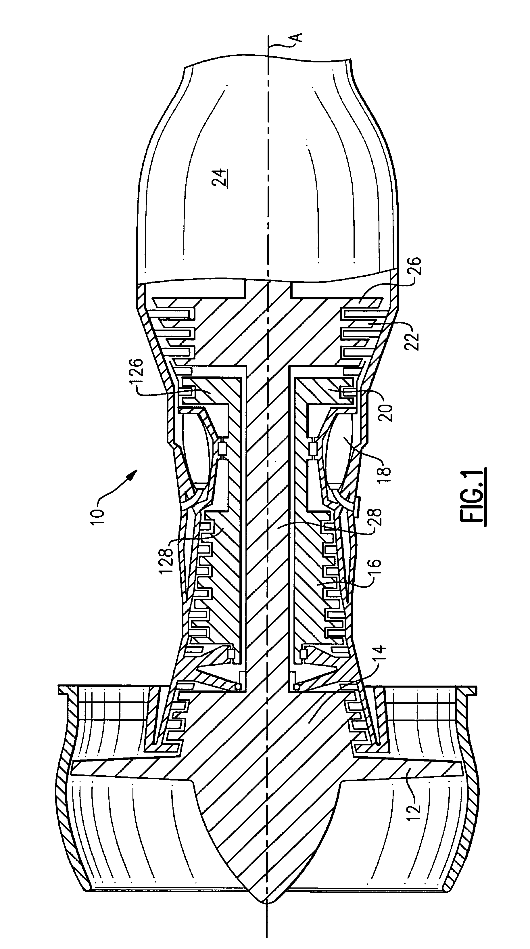
[0017]FIG. 1 is a schematic view of a gas turbine engine 10, such as a turbofan gas turbine engine. The engine 10 is circumferentially disposed about an engine centerline axis A. Air is pulled into the turbine engine 10 by a fan 12 and flows through a low pressure compressor 14 and a high pressure compressor 16. Air compressed in the compressors 14 and 16 is mixed with fuel which is burned in the combustion section 18 and expanded in a high pressure turbine 20 and a low pressure turbine 22 prior to leaving the engine 10 through an exhaust nozzle 24. The turbine 22 includes a rotor 26 which drives an engine shaft 28. A rotor 126 in turbine 20 drives a shaft 128 to in turn drive compressor 16. Rotation of the engine shaft 28 drives the fan 12 and compressor 14.

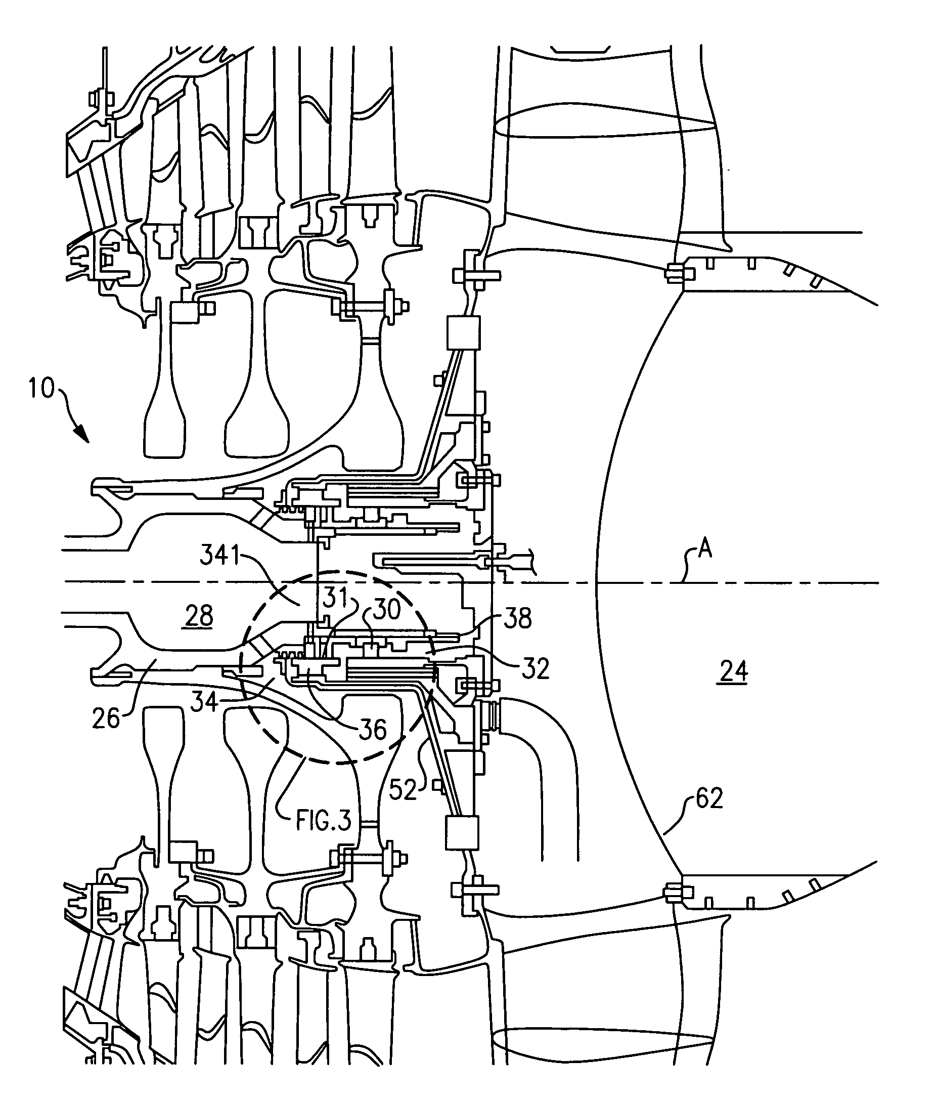
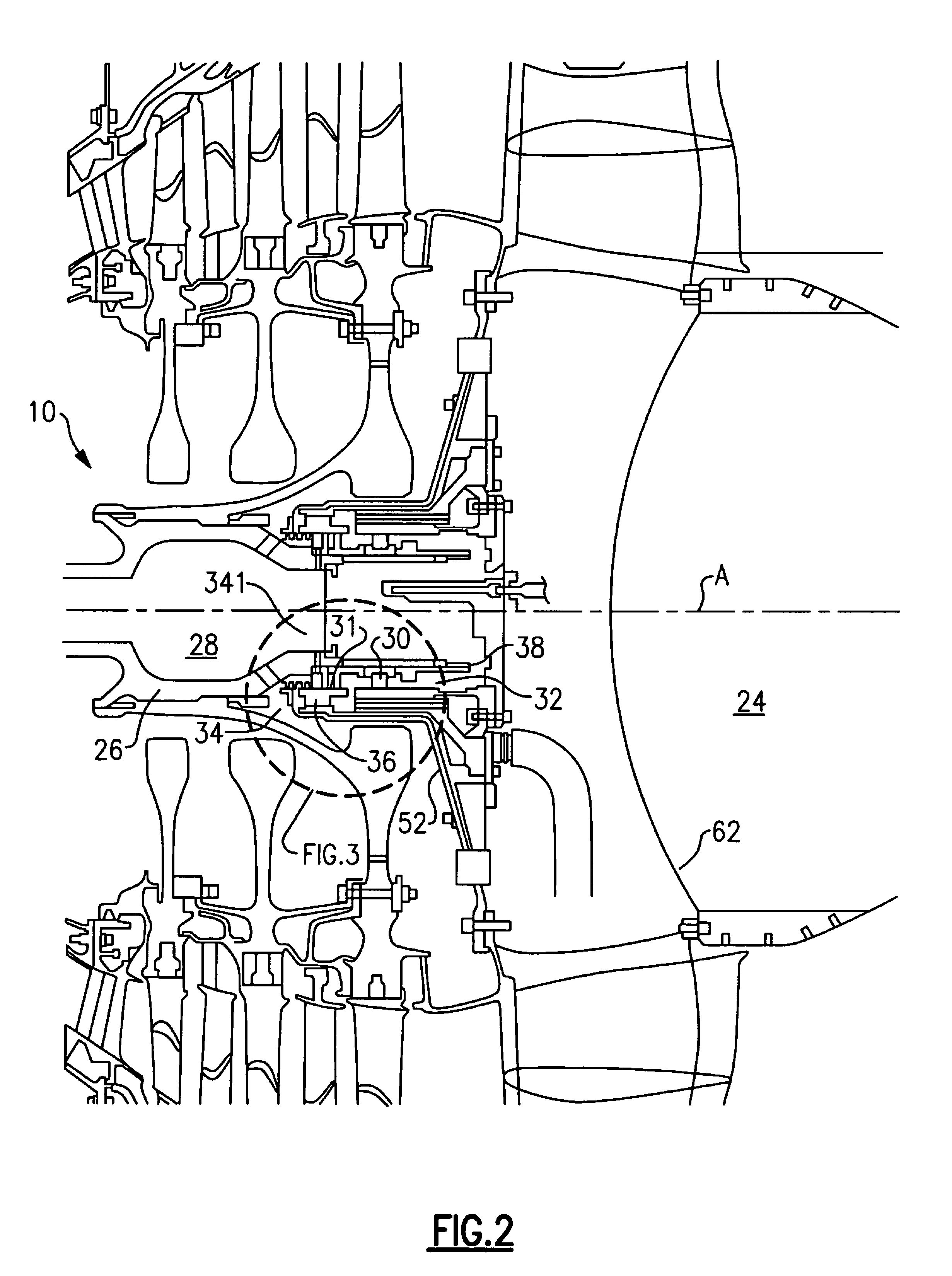
[0018]FIG. 2 is a view of a portion of the rear of the turbine engine 10 with a bearing seal 31 located between a rear bearing compartment 32 and an air compartment 34. The bearing seal seat 311 is mounted to and rotates with th...


PUM


Abstract

A turbine engine utilizes an oil director to direct any leakage oil from a rear bearing compartment of the turbine engine toward a drain opening for an oil drain. The oil drain is formed in a heat shield located between the low pressure turbine and the exhaust nozzle. The oil drain directs the leakage oil to a benign area of the turbine engine.

Description

BACKGROUND OF THE INVENTION[0001]The present invention relates generally to a rear bearing compartment for a turbine engine and more particularly, to an arrangement for capturing leakage oil from the rear bearing compartment.[0002]Turbine engines utilize bearings for supporting rotor operation. Oil is contained in a bearing compartment. Bearing seals are used to contain the oil in the bearing compartments so the oil will not leak into hot areas of the turbine engine. Any oil leakage from the bearing compartments must be managed so the oil does not collect in areas within the turbine engine that may become a fire hazard.[0003]Typically, secondary air pressurization and bearing compartment design are sufficient to prevent oil leakage from the bearing compartment. In addition to secondary air pressurization, front bearing compartments sometimes utilize oil drain systems, or “scupper systems”, to capture and drain leakage oil to benign areas of the turbine engine. Scupper systems have n...

Claims


Application Information

Patent Timeline
Patent Type & Authority Patents(United States)
IPC IPC(8): F01D5/08F01D5/18F01D11/00F04D29/00F01D25/00
CPCF01D25/125F01D25/186F02C7/06F02C7/28F05D2260/602F05D2240/55F05D2240/70
Inventor DIBENEDETTO, ENZO
Owner RTX CORP
Why Eureka
Try Eureka