Pre-amplifier and mixer circuitry for a locator antenna

a mixer circuit and locator technology, applied in thermoelectric instruments, using reradiation, instruments, etc., can solve problems such as messy and expensive cleanup efforts, serious injury and property damage, and disrupt the comfort and convenience of residents

Active Publication Date: 2011-06-28
SEEKTECH
View PDF3 Cites 25 Cited by
  • Summary
  • Abstract
  • Description
  • Claims
  • Application Information

AI Technical Summary

Problems solved by technology

If excavation equipment such as a backhoe hits a high voltage line or a gas line, serious injury and property damage may result.
Unintended severing of water mains and sewer lines generally leads to messy and expensive cleanup efforts.
The unintended destruction of power and data cables may seriously disrupt the comfort and convenience of residents and bring huge financial costs to business.
The accuracy of portable utility locators is limited by the sensitivity of their antennas.
Signal interference caused by capacitance or inductance within the antenna structures causes resonance and interference.
Additionally, methods of processing signals detected by antennas in portable utility locators by amplifying them and mixing them, have traditionally suffered from inefficiencies which include vulnerability to radio-frequency interference (RFI) and electromagnetic interference (EMI), and the introduction of undesirable capacitance and inductance.

Method used


Image

  • Pre-amplifier and mixer circuitry for a locator antenna
  • Pre-amplifier and mixer circuitry for a locator antenna
  • Pre-amplifier and mixer circuitry for a locator antenna

Examples


Embodiment Construction

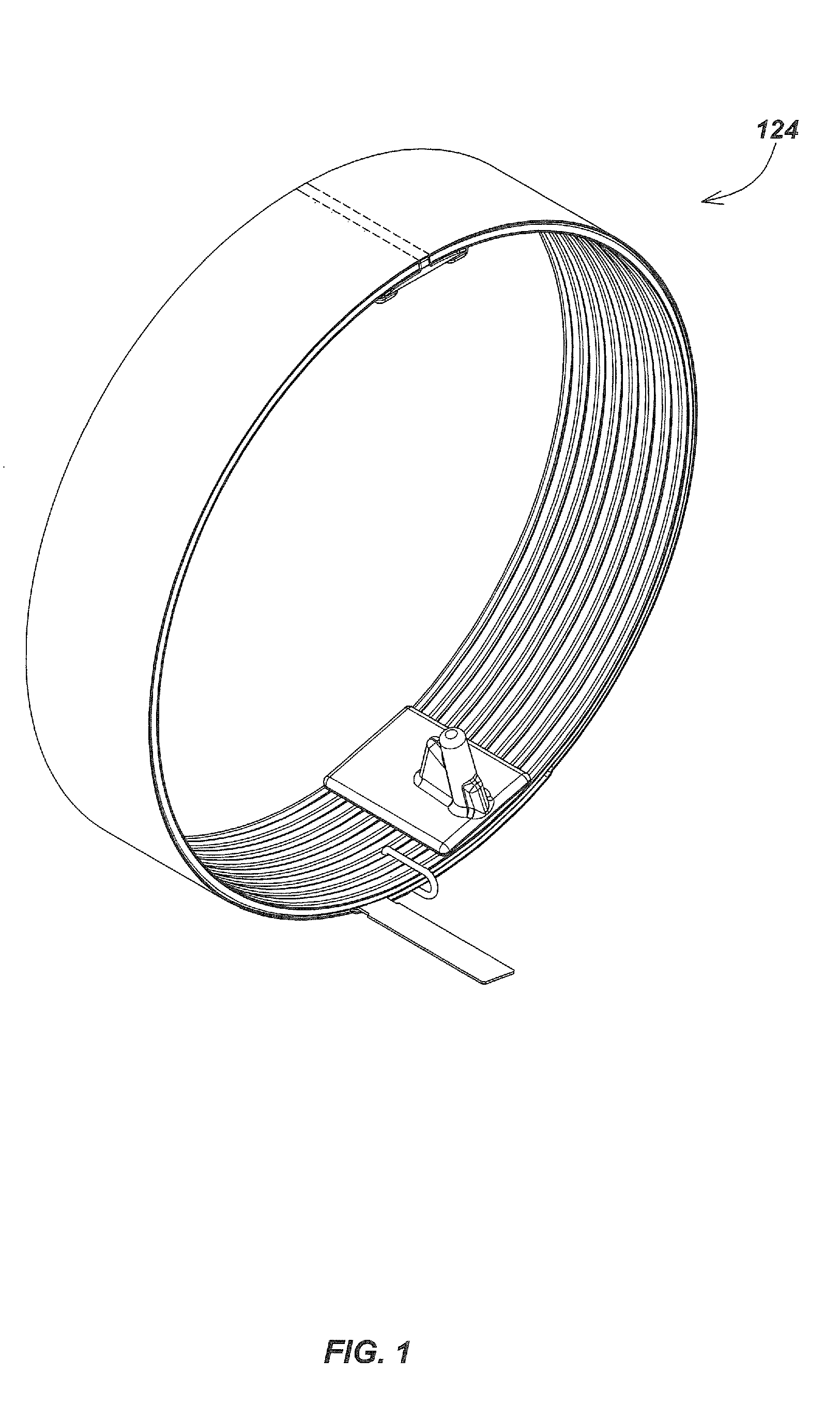
[0017]The present invention provides antenna interface circuitry particularly suited for use with an antenna for detecting electromagnetic fields in a human-portable utility locator such as that disclosed in co-pending U.S. patent application Ser. No. 11 / 248,539 filed by Mark S. Olsson, et al. on Oct. 12, 2005 and entitled “Reconfigurable Portable Locator Employing Multiple Sensor Array Having Flexible Nested Orthogonal Antennas,” the entire disclosure of which is incorporated herein by reference.

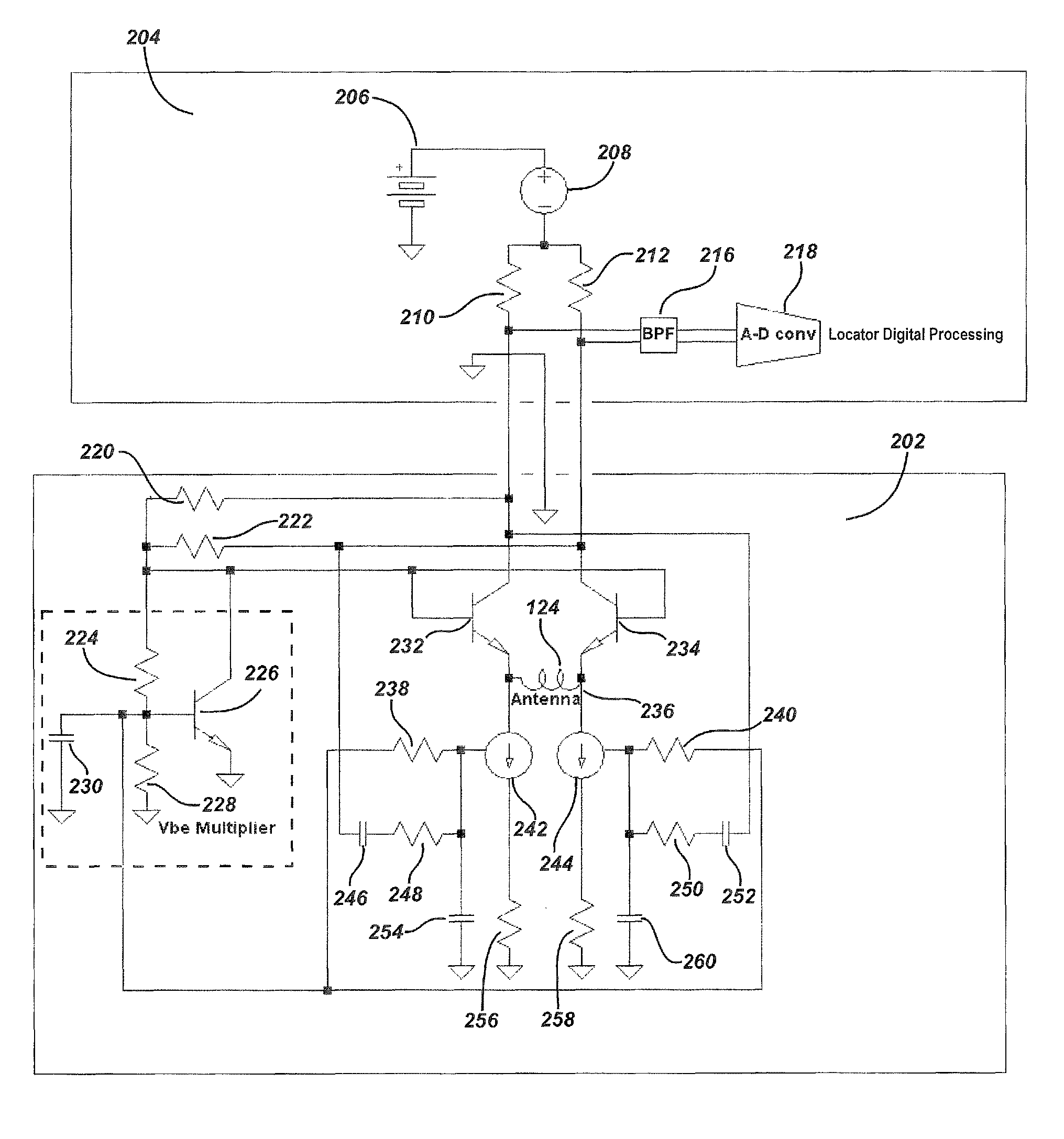
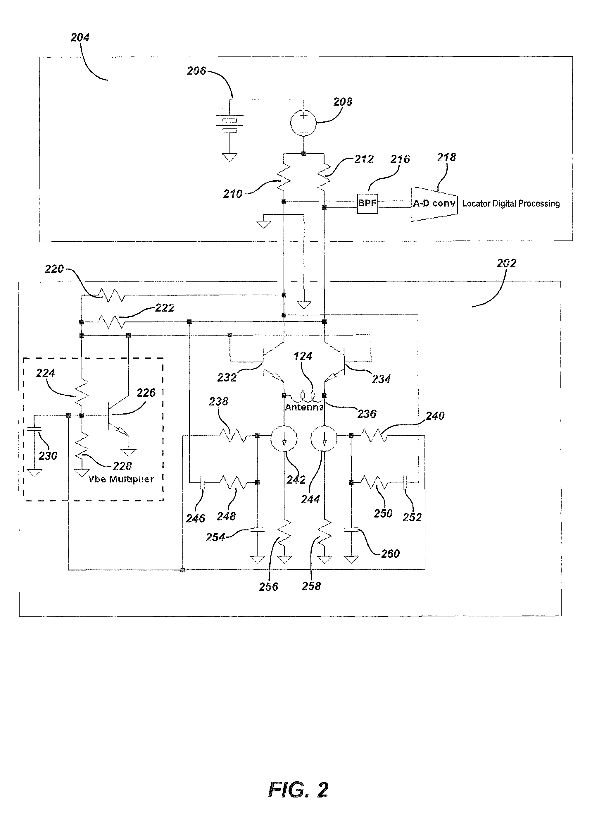
[0018]In accordance with this invention, a pre-amplifier circuit for connection to an antenna of a man-portable locator includes an amplifier / mixer and circuit that allows a common-mode phantom signal to modulate a transfer function of the amplifier / mixer.

[0019]The circuitry of this invention employs the repeatable temperature characteristics of a semiconductor p-n junction in the pre-amplifier to control the temperature dependence of the amplifier / mixer, which opposes the effects of the re...


PUM


Abstract

A pre-amplifier circuit for connection to an antenna of a human-portable locator includes a differential amplifier / mixer pair and means for allowing a common-mode “phantom” signal to modulate a transfer function of the differential amplifier / mixer pair. The common-mode phantom signal modulates the transfer function of the differential pre-amplifier “onboard” the antenna without the usual requirement for onboard power supply and signal oscillator. This technique uses the same electronic components to provide both pre-amplification and mixing functions, thereby improving circuit performance-to-cost ratio, reducing mixer power consumption, situating the necessary signal oscillator remotely from the mixer, and greatly improving the available system bandwidth by limiting spectral transmission demands to the mixed signal bandwidth alone.

Description

CROSS-REFERENCES TO RELATED APPLICATION[0001]This application claims the benefit, pursuant to 35 U.S.C.§§119-120, of the filing date of U.S. Provisional Application Ser. No. 61 / 027,212, entitled “CONDUCTIVE BOBBINS AND MIXING,” filed on Feb. 8, 2008, the disclosure of which is hereby entirely incorporated by reference.[0002]This application also claims the benefit, pursuant to 35 U.S.C. §§119-120, of the filing date of U.S. Provisional Application Ser. No. 61 / 033,272, entitled “PRE-AMPLIFIER AND MIXER CIRCUITRY FOR A LOCATOR ANTENNA,” filed on Mar. 3, 2008, the disclosure of which is hereby entirely incorporated by reference.[0003]This application is related by inventorship and subject matter to co-pending U.S. patent application Ser. No. 11 / 248,539 filed by Mark S. Olsson, et al. on Oct. 12, 2005 and entitled “Reconfigurable Portable Locator Employing Multiple Sensor Array Having Flexible Nested Orthogonal Antennas,” the entire disclosure of which is hereby incorporated by referenc...

Claims


Application Information

Patent Timeline
Patent Type & Authority Patents(United States)
IPC IPC(8): G01V3/08G01R21/14
CPCG01V3/101
Inventor BENCH, STEPHEN M.
Owner SEEKTECH
Why Eureka
Try Eureka