Integrated multi-function light guide for LCD backlighting

a multi-functional, light guide technology, applied in the direction of planar/plate-like light guides, lighting and heating apparatus, instruments, etc., can solve the problems of reducing system efficiency, dbef and bef are relatively expensive, and add to the cost of backlight units, etc., to achieve enhanced display brightness, low cost, and low index difference

Active Publication Date: 2011-06-28
JABIL CIRCUIT INC
View PDF6 Cites 84 Cited by
  • Summary
  • Abstract
  • Description
  • Claims
  • Application Information

AI Technical Summary

Benefits of technology

[0016]Integrated light guides with a unique coupling concept provide polarized light output with controlled angular light distribution in two orthogonal directions for LED-based flat panel displays. The novel structure eliminates the DBEF and BEF used in conventional LCD backlighting units.
[0017]In the novel light guide of this invention, micro-groove structures filled with birefringent (double refraction) material are provided on the front wall of the light guide for polarized light output. The light extraction is based upon total internal reflection (TIR). It has high efficiency and works for all colors (frequencies) of light. The angular distribution of output light depends upon the curved or angular profiles of those micro-structures and the index difference between the light guide material and the birefringent materia

Problems solved by technology

The DBEF and BEF are relatively expensive.
The use of both DBEF and BEF adds cost to the backlight unit and reduces system efficiency by causing light loss.
However, it is difficult to economically manufacture nano-scale features on the front wall of a PMMA light guide.
Moreover, the SWG alone cannot control the light extraction angle so a BEF is still needed for angle management.
However, the efficiency of this approach and it

Method used


Image

  • Integrated multi-function light guide for LCD backlighting
  • Integrated multi-function light guide for LCD backlighting
  • Integrated multi-function light guide for LCD backlighting

Examples


Embodiment Construction

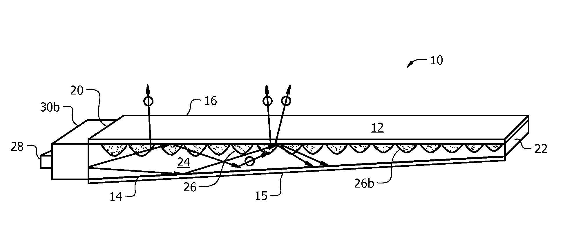
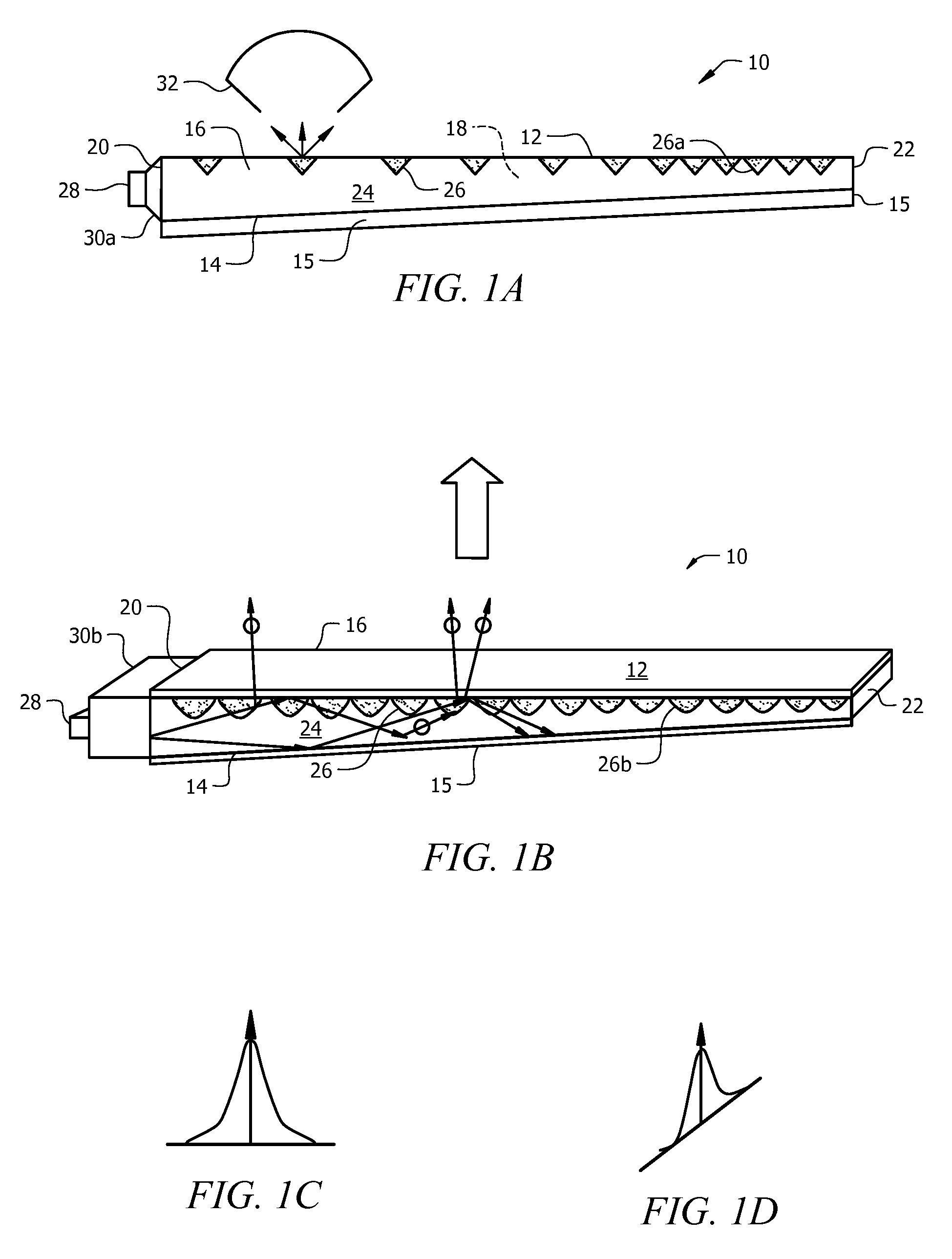
[0049]Referring now to FIGS. 1A and 1B, it will there be seen that an illustrative embodiment of the invention is denoted as a whole by the reference numeral 10.

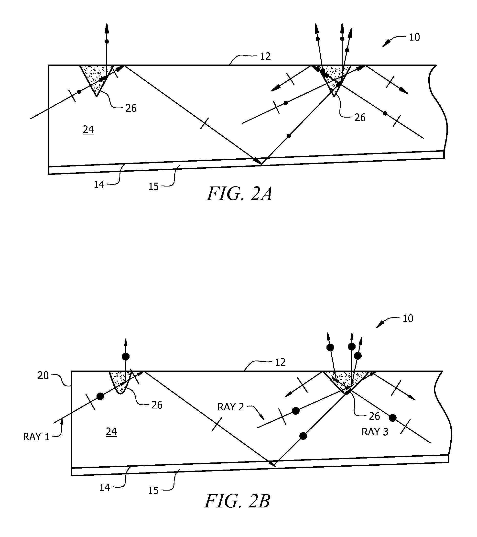
[0050]Elongate light guide 10 is a six-faced polyhedron and therefore includes a front wall 12, a back wall 14, top wall 16, bottom wall 18, and end walls 20, 22. In this first embodiment, back wall 14 is oblique with respect to front wall 12, i.e., the left end of back wall 14 is further from the left end of front wall 12 than the right end of back wall 14 is from the right end of front wall 12. A layer of retardation (QWP) and reflection film 15 is attached to back wall 14 and right end wall 22.

[0051]A plurality of microlenses, collectively denoted 26a in FIGS. 1A and 26b in FIG. 1B, is formed in front wall 12. As drawn in FIG. 1A, microlenses 26a from the left end of light guide 10 are spaced apart from one another by a predetermined distance, and such microlenses are closer together as they approach the right end of the ...


PUM


Abstract

A backlighting apparatus for a flat panel LCD display includes an elongate light guide having a front wall through which travels polarized light in a direction toward the LCD display. An RGB LED set is positioned adjacent a first end wall of the light guide so that light enters the light guide from the first end wall. A retardation and reflection film covers respective external surfaces of the bottom wall and a second end wall. Microlenses are formed in the front wall along its extent and each microlens is filled with a birefringent material. Light emitted by the LED set travels through a collimated light coupling module and exits the light guide through the birefringent microlenses in polarized form toward the LCD display. The viewing angles and angular light distributions of the LCD display in vertical and horizontal directions are optimized for enhancing the brightness without involving DBEF and BEF.

Description

CROSS-REFERENCE TO RELATED DISCLOSURES[0001]This disclosure is a nonprovisional of U.S. provisional patent application No. 60 / 893,778, filed Mar. 8, 2007 by the present inventors under the same title. That disclosure is hereby incorporated by reference in its entirety into this disclosure.1. FIELD OF THE INVENTION[0002]This invention relates, generally, to backlight illumination of flat panel LCD displays. More particularly, it relates to such illumination performed by a very low number of light-emitting diodes with the capacity to control the viewing angle and to provide polarized light output by means of a light guide.2. DESCRIPTION OF THE PRIOR ART[0003]Backlighting of flat panel LCD displays is conventionally provided by a layered arrangement of parts. The outermost layer is the LCD panel that a viewer sees and the innermost layer is formed by a plurality of CCFLs (cold cathode fluorescent lamps) that provide backlight illumination. A layer of DBEF (dual brightness enhancement f...

Claims


Application Information

Patent Timeline
IPC IPC(8): G02F1/13357F21V8/00
CPCG02B6/0056G02B6/0036G02B6/0016G02B6/0018G02B6/003G02B6/0061G02B6/0046
Inventor LI, LINMOREJON, ISRAEL J.ZHAI, JINHUIO'SULLIVAN, EVAN
Owner JABIL CIRCUIT INC
Why Eureka
Try Eureka