Neutralizer

a technology of neutralizer and ac, which is applied in the field of neutralizer, can solve the problems of deviating residual potential, difficult to build a smaller and lighter ac-type neutralizer, and avoiding types of neutralizers, etc., and achieves the effects of enhancing the neutralization potential, reducing residual potential, and improving attenuation time characteristics

Inactive Publication Date: 2011-07-05
MIDORI ANZEN
View PDF23 Cites 9 Cited by
  • Summary
  • Abstract
  • Description
  • Claims
  • Application Information

AI Technical Summary

Benefits of technology

[0022]The neutralizer is configured to apply the two rectangular-wave DC high voltages with polarities different from each other to the first and second groups in the discharger, respectively. For this reason, the neutralizer can produce a larger number of positive and negative ions than the AC-type neutralizer, and is thus capable of making the attenuation time characteristic better. For the same reason, the neutralizer can make the neutralization range wider than the AC-type neutralizer does.
[0023]The neutralizer is configured to produce positive and negative ions during the same period from the discharge needles of the two groups thus divided. Concurrently, the neutralizer according is configured to reverse at regular intervals the polarity of ions outputted from each group. For this reason, the neutralizer can simultaneously produce positive and negative ions during the same period, and is thus capable of making the number of positive ions and the number of negative ions almost equal to each other on the front surface of the neutralization target object. Accordingly, the neutralizer enhances neutralization of the potential, and is thus capable of reducing the residual potential on the front surface of the neutralization target object. Consequently, the neutralizer can make the variation of ion balance nearly equal to zero, and can concurrently reduce the deviation of the variation.
[0024]In addition, the neutralizer is configured to reverse the polarities of positive and negative ions emitted at regular intervals, and is concurrently configured to switch places from which positive and negative ions are emitted at regular intervals. For this reason, the neutralizer can prevent the neutralization target object from being affected by either positive or negative ions depending on where the neutralization target object is located, and is thus capable of almost evenly irradiating positive and negative ions onto the neutralization target object located any places. Consequently, the neutralizer can minimize the spatial deviation of ion balance.
[0025]Moreover, the neutralizer is configured to reverse at regular intervals the polarities of positive and negative ions emitted from the discharge needles of the groups. For this reason, even when the neutralizer is continuously operated, the discharge needles of each group become almost equally fouled with dirt, eroded and abraded. Consequently, the residual potentials of the discharge needles do not deviate, and the temporal deviation of ion balance can be reduced.

Problems solved by technology

In addition, the temporal deviation of ion balance means that, to while a neutralizer is continuously operated, the residual potential deviates due to differences between positive and negative discharge needles in the degrees of dirt adhesion, erosion and abrasion.
The foregoing types of neutralizers, however, have problems as follows.
However, it is difficult to build a smaller and lighter AC-type neutralizer.
As a result, the AC type neutralizer has difficulty in keeping the residual potential close to zero volts after ion irradiation.
Moreover, the AC type neutralizer produces less positive and negative ions than the DC type neutralizer does, and thus is inferior to the DC type neutralizer in terms of the attenuation time characteristic and the neutralization range.
This causes a temporal deviation of ion balance.
In addition, depending on where the discharge needles are located, some places are more susceptible to positive ions, and others are more susceptible to negative ions.
This makes it difficult to cause ions to travel far.
In addition, less ions reaching the object lead to deterioration in the attenuation time characteristic.
As described above, the conventional types of neutralizers have problems in any of size, weight, attenuation time characteristic, or ion balance characteristic.
Currently, there has been developed no neutralizer that overcomes all these problems.

Method used


Image

  • Neutralizer
  • Neutralizer
  • Neutralizer

Examples


Embodiment Construction

[0034]Descriptions will be hereinblow provided for an embodiment of a neutralizer according to the present invention on a basis of the drawings.

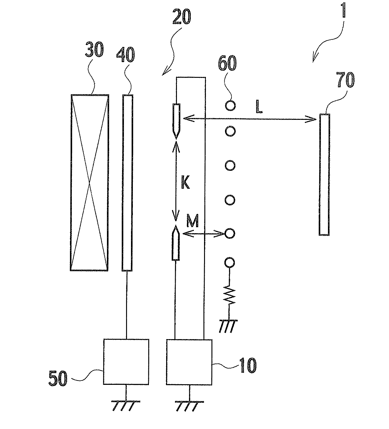
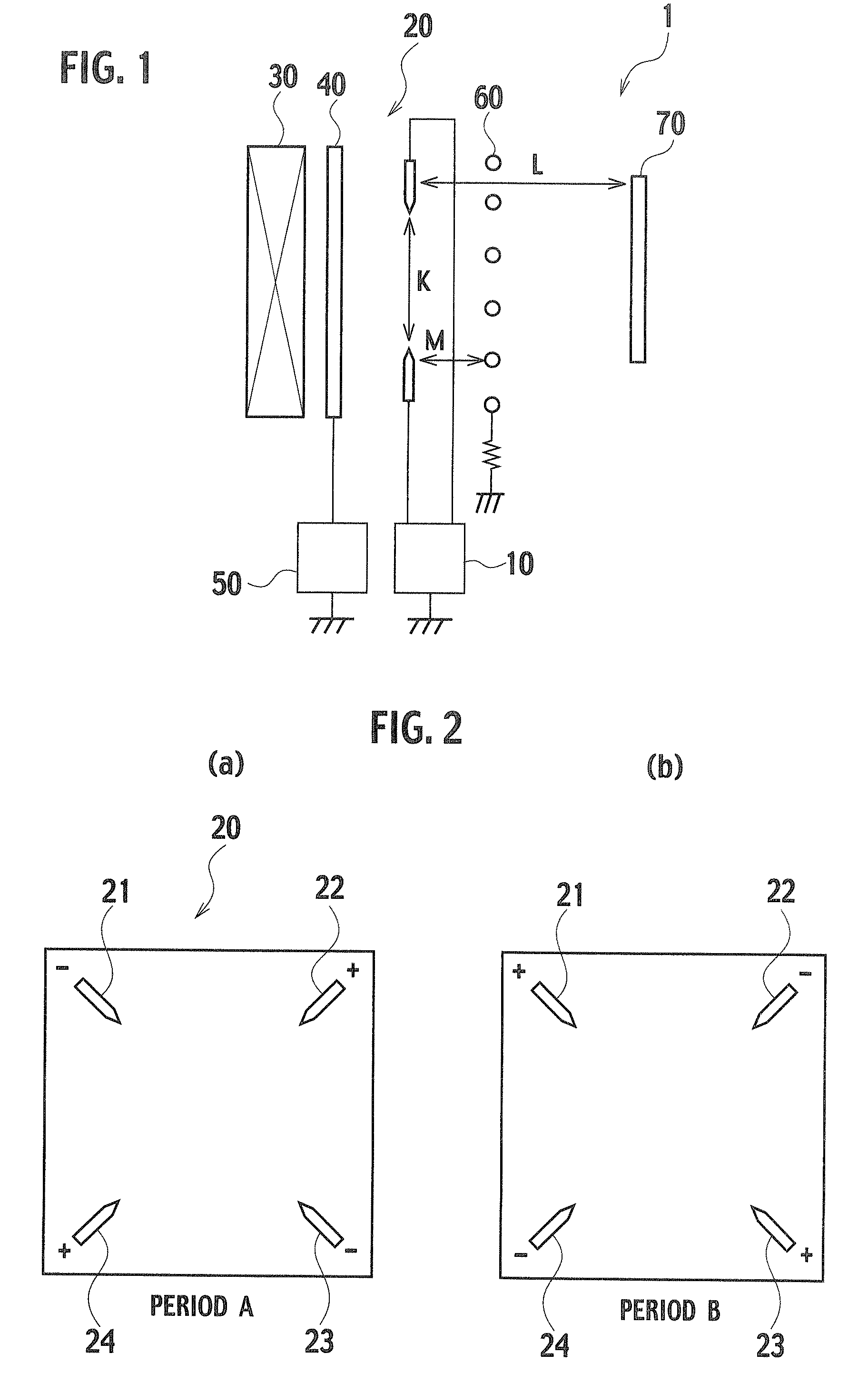
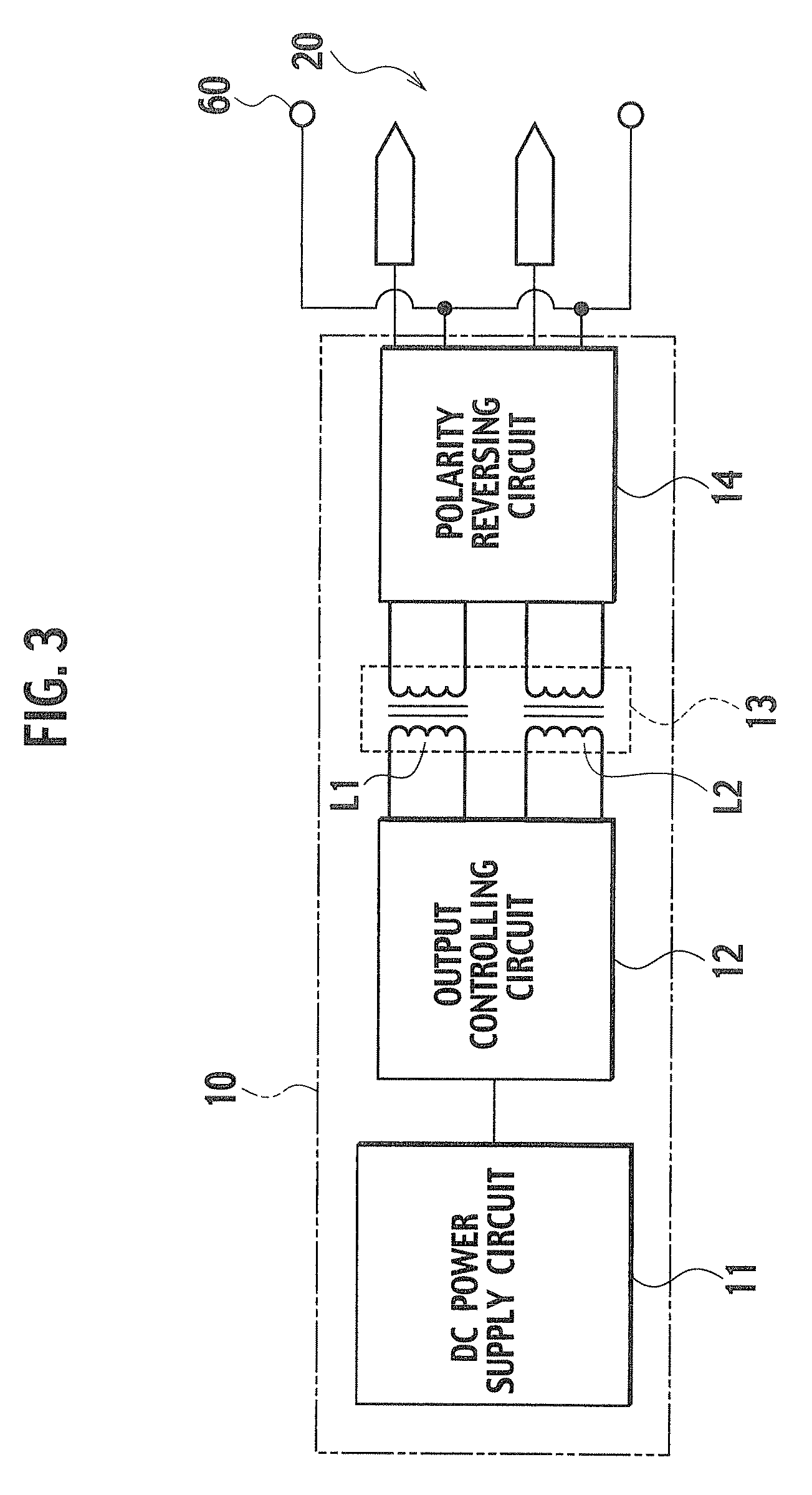
[0035]FIG. 1 is a diagram of an overall configuration of the neutralizer according to the present embodiment, FIG. 2 is an explanatory diagram showing a configuration of a discharger, and FIG. 3 is a block diagram showing a configuration of a high-voltage-generating circuit.

[0036]As shown in FIG. 1, the neutralizer 1 includes a high-voltage-generating circuit 10, a discharger 20, an air blower 30, an electrode 40 for detecting the pulsed streamer-corona, a detecting device 50 of the pulsed streamer-corona signal and a guard electrode 60. Reference numeral 70 denotes a neutralization target object.

[0037]The high-voltage-generating circuit 10 is a circuit configured to simultaneously apply DC high voltages with different polarities to the discharger 20 in an alternate manner at regular intervals. Descriptions will be provided for the configura...


PUM


Abstract

A neutralizer 1 includes: a power supply circuit 11; an output controlling circuit 12 configured to convert a DC voltage generated by the power supply circuit 11 to a high-frequency voltage with frequency equal to or higher than an audible frequency, and thus to output the resultant high-frequency voltage alternately to two output lines at regular intervals; a transforming circuit 13 configured to raise the high-frequency voltage; a discharger 20 including 2n (n is an integer equal to one or more) discharge needles configured to output positive ions in response to application of a positive polarity voltage, and to output negative ions in response to application of a negative polarity voltage, the discharge needles being disposed while being divided into first and second groups each including n discharge needles; a polarity reversing circuit 14 configured to convert the high-frequency high voltage outputted from the transforming circuit 13, to two rectangular-wave DC high voltages with different polarities during a certain period, and to output the two DC high voltages respectively to the first and second groups in the discharger 20 while reversing the polarities of the two DC high voltages at regular intervals; and an air blower configured to blow air from a windward side of the discharger 20.

Description

TECHNICAL FIELD[0001]The present invention relates to a neutralizer configured to electrically neutralize an electrostatically-charged object by irradiating the object with positive ions and negative ions.BACKGROUND ART[0002]Conventionally, in order to prevent electrostatic trouble and electrostatic adsorption due to electrostatical-charge of components, neutralizers are placed near working benches, conveyors and the like in a semiconductor device manufacturing line, a cell manufacturing process for mobile phones and the like. The neutralizers used in these working areas include neutralizers which: emit (irradiate) positive ions or negative ions onto a neutralization target object (a component) in which charges are unevenly distributed because positive charges or negative charges are excessive wholly or partially; and thereby electrically neutralize the object. These neutralizers are classified into some types depending on neutralization methods. Descriptions will be hereinbelow pro...

Claims


Application Information

Patent Timeline
Patent Type & Authority Patents(United States)
IPC IPC(8): H05F3/04H01T19/04H01T23/00
CPCH01T23/00H01T19/04
Inventor TSUMORI, TOMONORISUGITA, NAOKI
Owner MIDORI ANZEN
Why Eureka
Try Eureka