Starter for engines and its starting circuit

a technology for starting engines and starting circuits, applied in the direction of engine starters, electric generator control, magnetic bodies, etc., can solve the problems of increasing cost, inability to control the operating current directly by a switch with an ecu, etc., and achieve the effect of reducing the number of parts and cos

Active Publication Date: 2011-07-05
DENSO CORP
View PDF47 Cites 16 Cited by
  • Summary
  • Abstract
  • Description
  • Claims
  • Application Information

AI Technical Summary

Benefits of technology

[0017]The present invention has been made in order to solve the issue described above, and has as its object to provide a starter at lower cost by reducing the number of parts.
[0018]The present invention has another object to provide a starting circuit of the starter that realizes to lower the cost by reducing the number of the parts and simplifying the circuit composition.
[0020]According to the above-mentioned composition, the electromagnetic switch of the starter is a single coil type that generates the attraction force for attracting the plunger and the holding power for holding the plunger with one switch coil. In this case, the switch coil does not have to be connected to the starting circuit, thus the switch coil and the starting circuit are separated electrically. By this, a connecting terminal for connecting electrically of a conventional attracting coil and an M terminal bolt can be abolished, and the process of connecting an end of the attracting coil to the connection terminal by welding etc. becomes unnecessary. Consequently, the cost can be held low by the reductions of the numbers of the parts and the manufacturing processes.
[0026]As a result, the cost of the starter starting circuit can be lowered because of the simplified circuit composition, and reduced number of the parts.

Problems solved by technology

However, since the operating current for energizing the switch coil is large (about 40 amperes) for the electromagnetic switch with two coils, the operating current cannot be controlled directly by a switch with an ECU (electronic control unit).
With this composition, the number of parts increases, and a process for attaching the connecting terminal to the M terminal bolt and a process for connecting the end of the attracting coil 100 to the connecting terminal (welding) is also required, thus the cost would rise.

Method used


Image

  • Starter for engines and its starting circuit
  • Starter for engines and its starting circuit
  • Starter for engines and its starting circuit

Examples


Embodiment Construction

[0035]With reference to the accompanying drawings, hereinafter will be described an embodiment of the present invention.

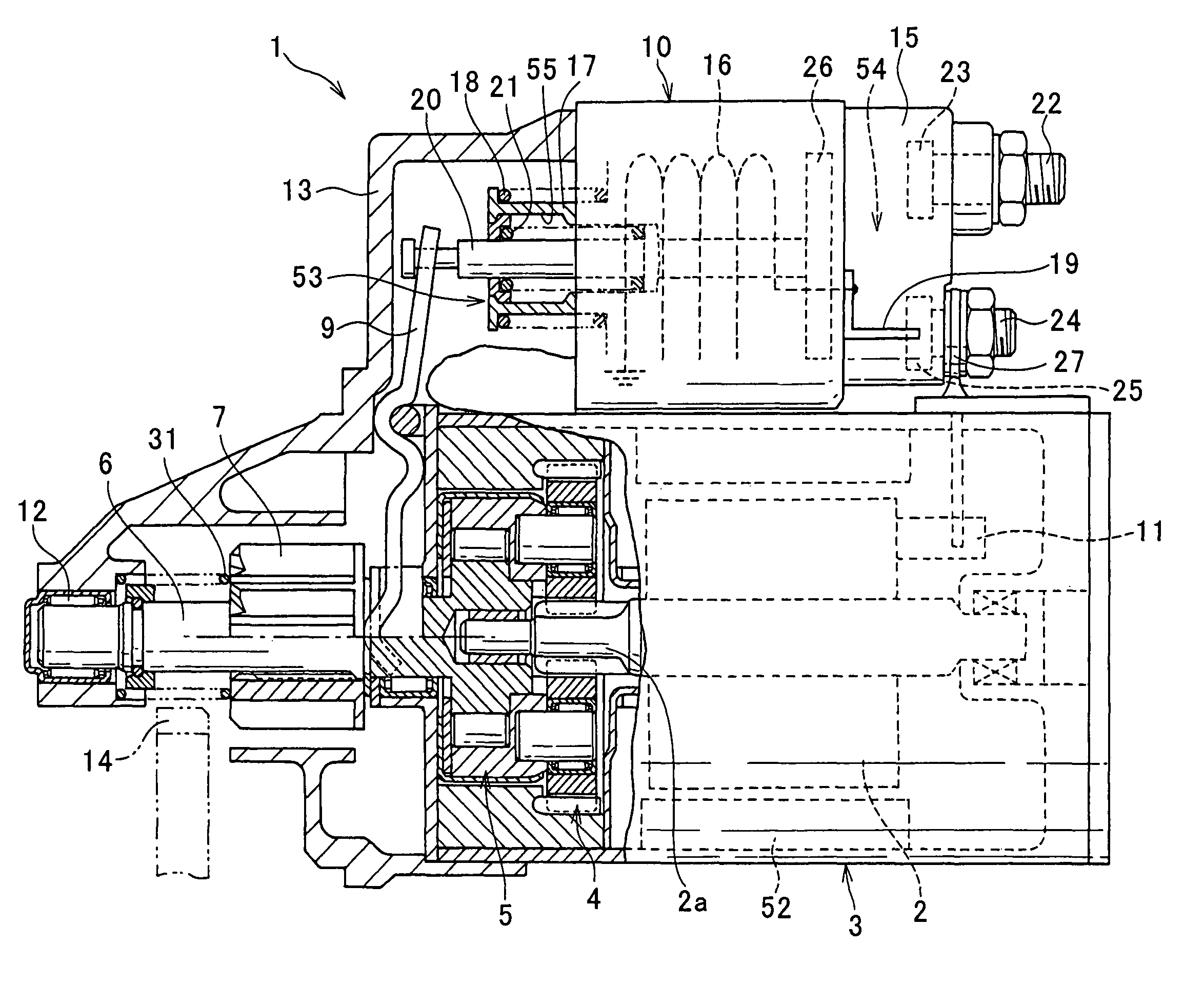
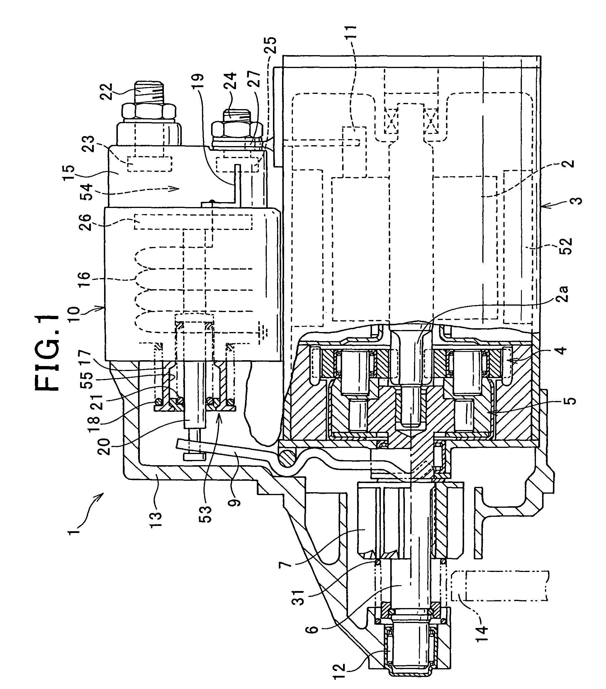
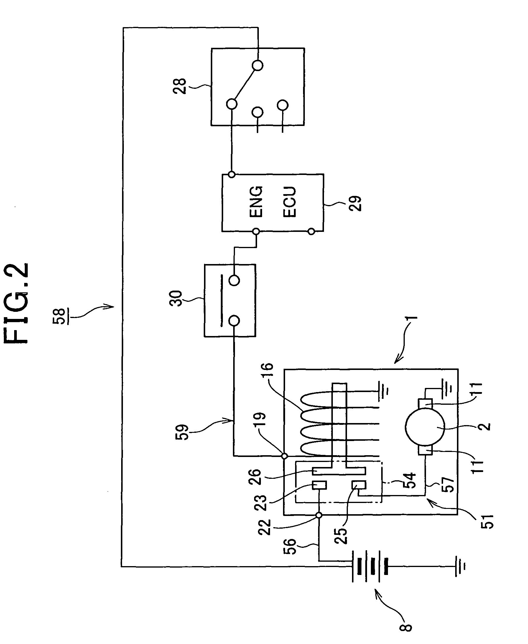
[0036]FIG. 1 is a side view of a starter containing a partial section and FIG. 2 is a starting circuit diagram of a starter.

[0037]As shows in FIG. 1, the starter 1 of this embodiment is comprised of a motor 3 which generates torque to an armature 2 that is build into the motor 3, a speed reducer 4 that slows down the rotation of the motor 3, an output shaft 6 connected to the speed reducer 4 via a clutch 5, a pinion gear 7 that engages in a helical spline manner to the perimeter of the output shaft 6, and a electromagnetic switch 10, etc. The electromagnetic switch 10 opens and closes a main point of contact (described later) provided in a motor circuit 51 for energizing the armature 2 from a battery 8 (referring to FIG. 2), and also pushes the pinion gear 7 towards the anti-motor side (left side in FIG. 1) via a shift lever 9.

[0038]The motor 3 is a commutator moto...


PUM


Abstract

The starter has a system of pushing the pinion gear in the direction of the anti-motor side by using the attracting power of the electromagnetic switch via the shift lever. The switch coil of the electromagnetic switch is constituted of one coil that is electrically separated from the motor circuit. The mass of pinion gear is set to 100 g or less, the switch extrusion power stored in the drive spring is set to 70N (Newton) or less, and the operation current of the electromagnetic switch is set to 12 amperes or less. With this starter, since the switch coil and the motor circuit can be electrically separated, the terminal for connection for connecting the conventional attracting coil and conventional “M terminal bolt” can be abolished. Further, by setting the operation current of the electromagnetic switch 10 to 12 amperes or less, it is possible to control the operation current directly by the ECU.

Description

CROSS-REFERENCE TO RELATED APPLICATION[0001]This application is based on and claims the benefit of priority from earlier Japanese Patent Application No. 2007-192336 filed Jul. 24, 2007, and Japanese Patent Application No. 2007-192389 filed Jul. 24, 2007, the description of which is incorporated herein by reference.BACKGROUND OF THE INVENTION[0002]1. Technical Field of the Invention[0003]The present invention relates to a starter for starting engines and its starting circuit, and in particular, to a starter having a system of pushing a pinion gear in the direction of an anti-motor side by using a shift lever driven by an electromagnetic switch.[0004]2. Description of the Related Art[0005]As disclosed in Japanese Patent No. 3478211, there is a starter for starting an engine with a conventional type of technology having a motor that generates a torque by energizing an armature and an electromagnetic switch that opens and closes a main point of contact provided in a motor circuit for en...

Claims


Application Information

Patent Timeline
Patent Type & Authority Patents(United States)
IPC IPC(8): H01H67/02F02N11/08F02N11/00H02P9/04
CPCF02N11/087F02N15/04F02N15/067F02N2011/0874
Inventor ANDOH, KAZUHIRO
Owner DENSO CORP
Why Eureka
Try Eureka