
Hybrid wheel and hybrid roadway

a hybrid and wheel technology, applied in the field of motor vehicles, can solve the problems of significant rolling resistance, inefficient door-to-door service of trains, hardness of steel wheels, etc., and achieve the effect of increasing the fraction of load

Inactive Publication Date: 2011-07-12
BULLIS JAMES KENNETH
View PDF11 Cites 12 Cited by
  • Summary
  • Abstract
  • Description
  • Claims
  • Application Information

AI Technical Summary

Benefits of technology

This hybrid system significantly reduces energy loss due to rolling resistance by up to a factor of ten, enhancing the efficiency of truck and automobile operations while minimizing damage and congestion, and enabling smoother transitions between road and rail surfaces.

Problems solved by technology

However, the steel wheels would work badly on most other road surfaces where abrasive effects would damage the steel wheels, and the hardness of the steel wheels would damage most road surfaces.
Rubber tired wheels work well on most road surfaces, but cause significant rolling resistance due to friction.
Being limited to operation on tracks, trains are inefficient in providing door to door service.
There is a separate congestion problem that arises from having a large number of rode vehicles on the roads, extensive though the network of such roads might be.
Even if aerodynamic drag forces are greatly reduced, we still have the problem of rolling resistance which is present at all speeds.
While this rolling resistance is a problem for automobiles, it is a much more serious problem for trucks where their great weight translates into large rolling resistance force due to the rubber tire friction effects.

Method used


Image

  • Hybrid wheel and hybrid roadway
  • Hybrid wheel and hybrid roadway
  • Hybrid wheel and hybrid roadway

Examples


Embodiment Construction

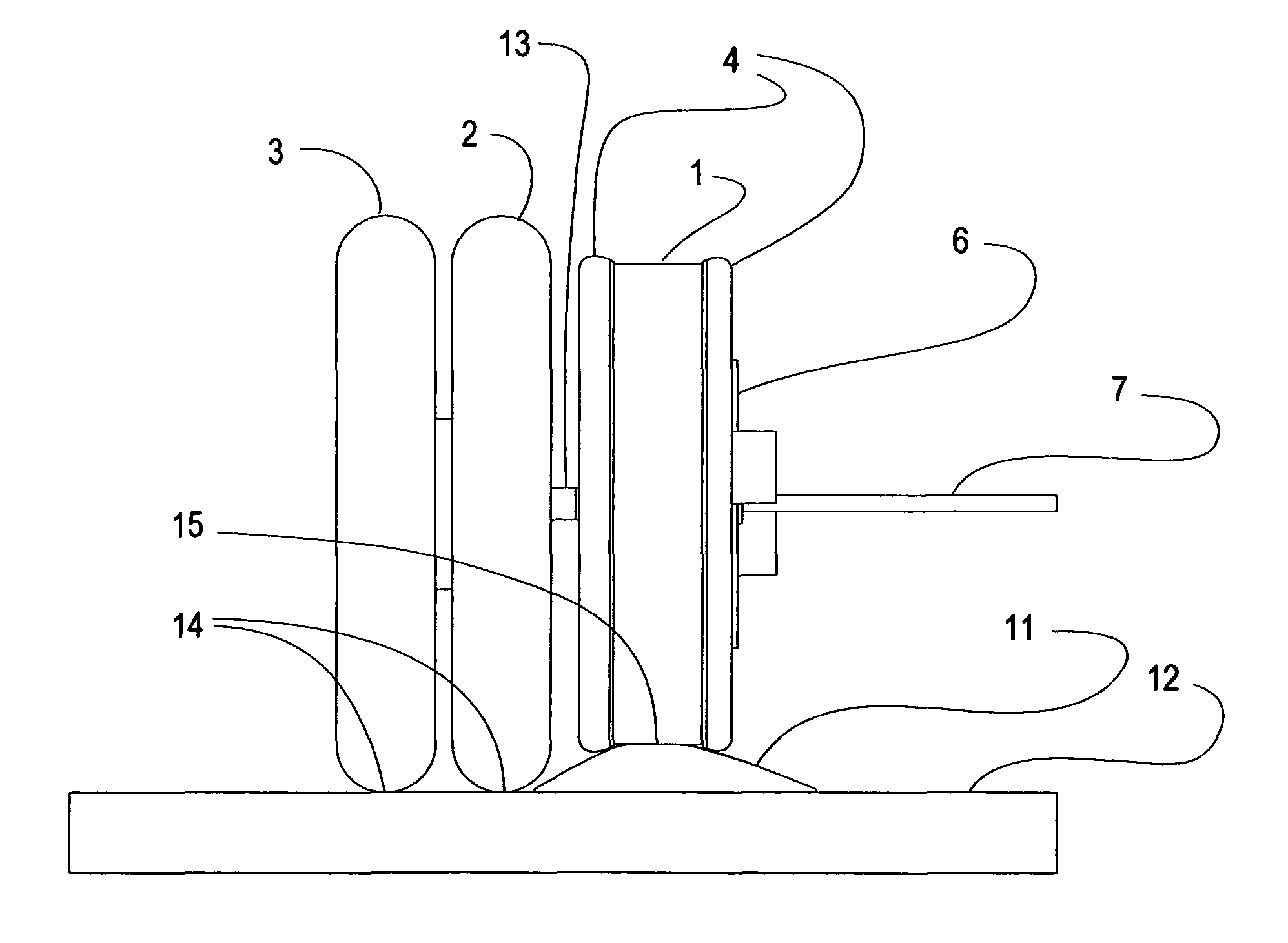
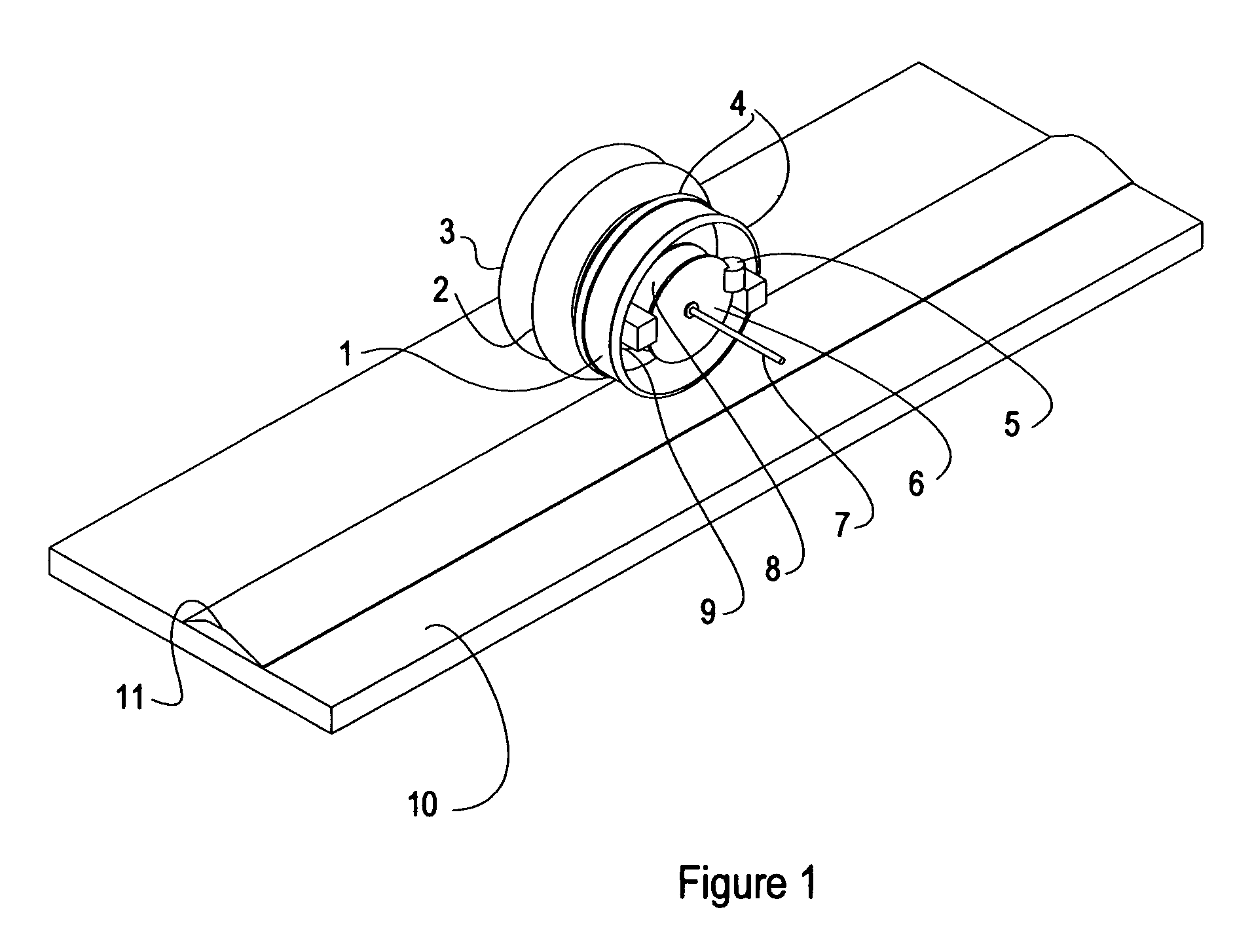
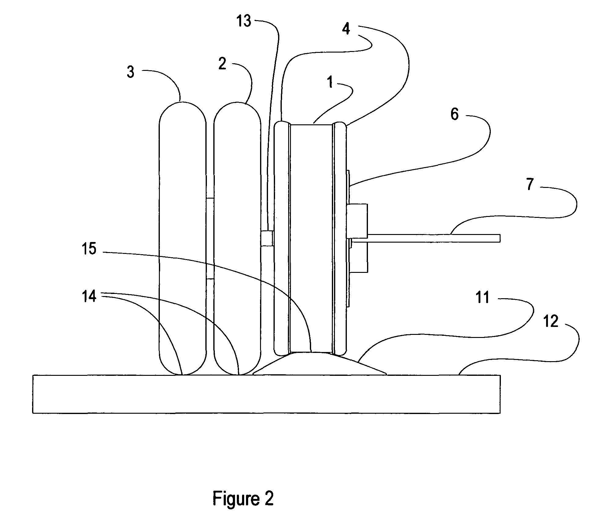
[0039]Here disclosed is a hybrid wheel apparatus with a hybrid roadway apparatus that reduces the energy lost due to rolling resistance by as much as a factor of ten, or even more. Truck wheels are the most immediate concern, though automobile wheels are also candidates to be replaced by the hybrid wheel systems.

[0040]The hybrid wheel is a steel wheel coaxially mounted with a rubber tired wheel, each wheel enabled to rotate about an axis at different rotation rates. The hybrid roadway is a low profile steel rail fixed to the otherwise plain road surface, which is preferably concrete, but could also be the very common asphalt composition.

[0041]The rail is elevated over the roadway surface and the steel wheel is of smaller diameter than the rubber tired wheel. Dimensions are set so that most of load force is carried on the steel wheel for general forward travel, but where the rail is absent the load is carried on the rubber tire. When the roadway is not fitted with a rail, contact bet...


PUM


Abstract

The invention is a hybrid wheel apparatus with a hybrid roadway apparatus that greatly reduces the energy lost due to rolling resistance where operation is on the hybrid roadway, but the system is configured to allow operation on conventional roads as needed.The hybrid wheel system is a steel wheel used in combination with a rubber tired wheel. The hybrid roadway is a low profile steel rail fixed to the otherwise conventional road surface, which is preferably concrete but could also be the very common asphalt composition.Where roadways are appropriately equipped with rails, the rail top surface is elevated over the roadway surface, and dimensions are set so that most of load force is carried on the steel wheel for general forward travel. Where the rail is absent the load is carried on the rubber tire, and the steel wheel is elevated above the roadway surface such that contact between the steel wheel and the roadway is prevented.

Description

[0001]This patent document contains material that is subject to copyright protection. Facsimile reproduction is allowed of the patent document or the patent disclosure as it appears in the Patent and Trademark Office patent file or records as allowed by US patent law, but otherwise all copyright rights are reserved.BACKGROUND OF THE INVENTION[0002]1. Field of the Invention[0003]This present invention relates to motor vehicles.[0004]2. Description of the Prior Art[0005]Steel wheels running on steel tracks roll with very little friction to make railroad trains very efficient. Such trains work well for point to point operation between terminals connected by the tracks. However, the steel wheels would work badly on most other road surfaces where abrasive effects would damage the steel wheels, and the hardness of the steel wheels would damage most road surfaces. Rubber tired wheels work well on most road surfaces, but cause significant rolling resistance due to friction.[0006]Being limit...

Claims


Application Information

Patent Timeline
Patent Type & Authority Patents(United States)
IPC IPC(8): B61C11/00
CPCB60B11/02B60B17/0072B60B17/0089B60B19/02B60T8/3235B61B13/00E01B2/00E01B25/00E01B25/28Y02T30/30B60C2003/005Y02T30/00
Inventor BULLIS, JAMES KENNETH
Owner BULLIS JAMES KENNETH
Learn More