Continuous sheet processing apparatus and method of setting a roll body in the continuous sheet processing apparatus

a processing apparatus and continuous sheet technology, applied in the direction of thin material processing, printing, filament handling, etc., can solve the problems of difficult operation of inserting the bobbin into the central hole of the roll body in the accommodating portion of the confined space of the roll body, inability to support the roll body thereafter, and difficulty in achieving the effect of easy structure realization, favorable operability and favorable transportation

Inactive Publication Date: 2011-07-12
SEIKO INSTR INC
View PDF5 Cites 14 Cited by
  • Summary
  • Abstract
  • Description
  • Claims
  • Application Information

AI Technical Summary

Benefits of technology

[0017]It is therefore an object of the present invention to provide a continuous sheet processing apparatus in which, even with a structure in which setting of the roll body in the roll body accommodating portion is extremely easy, it is possible to stably transport the continuous sheet drawn out from the roll body without causing the irregular movements such as the lifting up of the roll body, and a method of setting a roll body in the continuous sheet processing apparatus.

Problems solved by technology

In the first related art example described above, there are required an operation of inserting the central shaft into the central hole of the roll body and an operation of attaching the central shaft holding the roll body to the frame, thereby being troublesome.
Further, in order to prevent a situation where the central shaft detachable with respect to the frame is lost by mistake, thereby making supporting of the roll body thereafter impossible, a user must be cautious.
After that, when there is a need for a new roll body to be used, the central shaft is not available, so there may arise a problem in that holding of the roll body cannot be performed.
However, the operation of inserting the bobbin into the central hole of the roll body in a confined space of the roll body accommodating portion is extremely complicated.
Specifically, positioning of the fitting portion of the bobbin with respect to the central hole of the roll body by fumbling of the user, and moving the fitting portion of the bobbin with respect to the frame to insert the fitting portion into the central hole are extremely complicated.
In particular, in a case where a clearance between the fitting portion of the bobbin and the central hole of the roll body is smaller, positioning and insertion operations become more complicated.
Further, at a time of positioning or attaching, there is a risk of damaging a side portion of the roll body by a tip of the fitting portion of the bobbin, thereby leaving a flaw or deformation in an edge portion of the continuous sheet.
As a result, the continuous sheet 1 cannot be correctly supplied to the processing portion 3.
Therefore, there occurs operation failures, in which, for example, the continuous sheet 1 is transported while being oriented obliquely, a transport speed becomes nonuniform, and finally, the transportation is impossible.
Further, there is a risk of causing abnormalities in processing by a processing head 4 of the processing portion 3, such as printing failure, and variation in or absence of thermal activation.

Method used


Image

  • Continuous sheet processing apparatus and method of setting a roll body in the continuous sheet processing apparatus
  • Continuous sheet processing apparatus and method of setting a roll body in the continuous sheet processing apparatus
  • Continuous sheet processing apparatus and method of setting a roll body in the continuous sheet processing apparatus

Examples


second embodiment

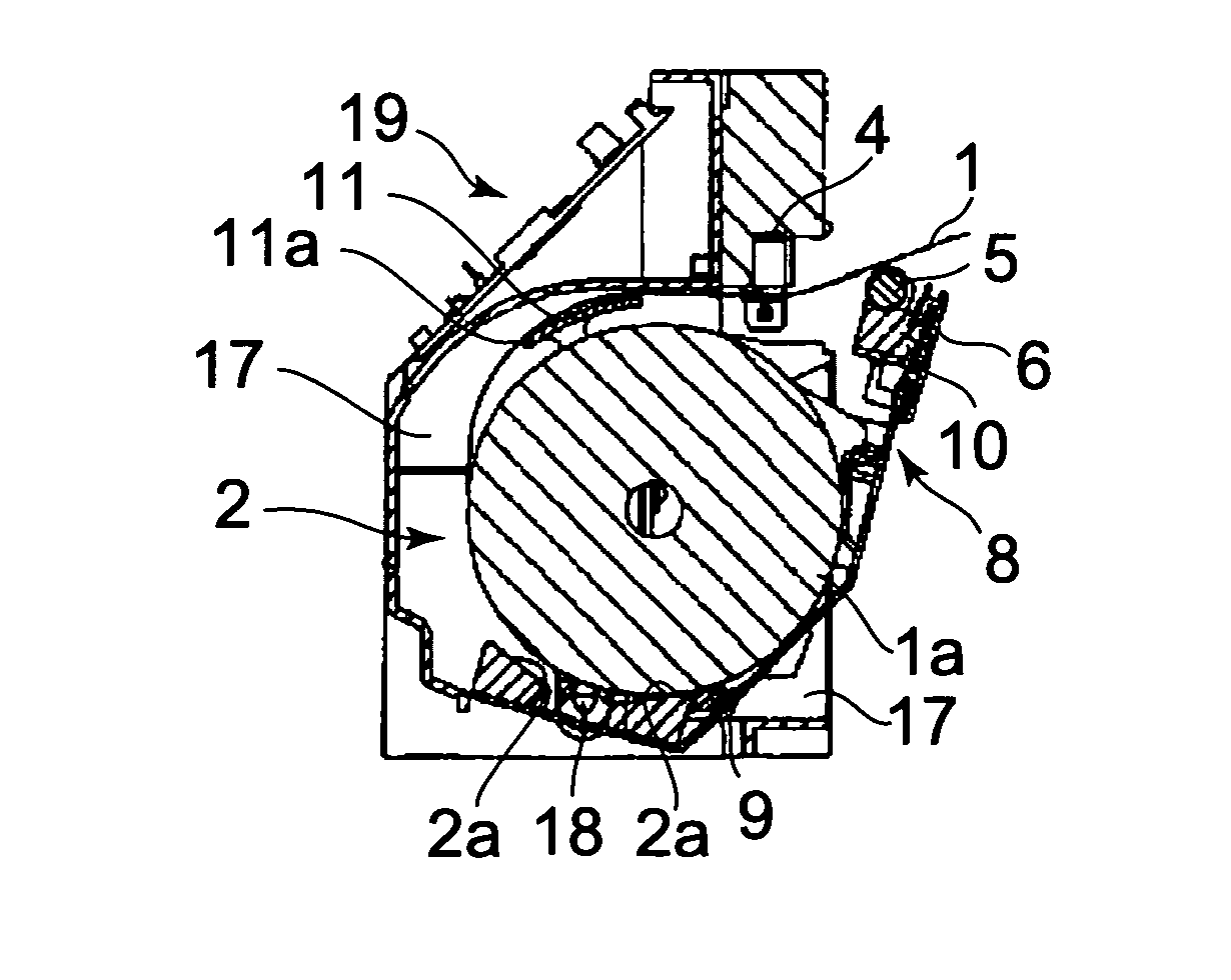
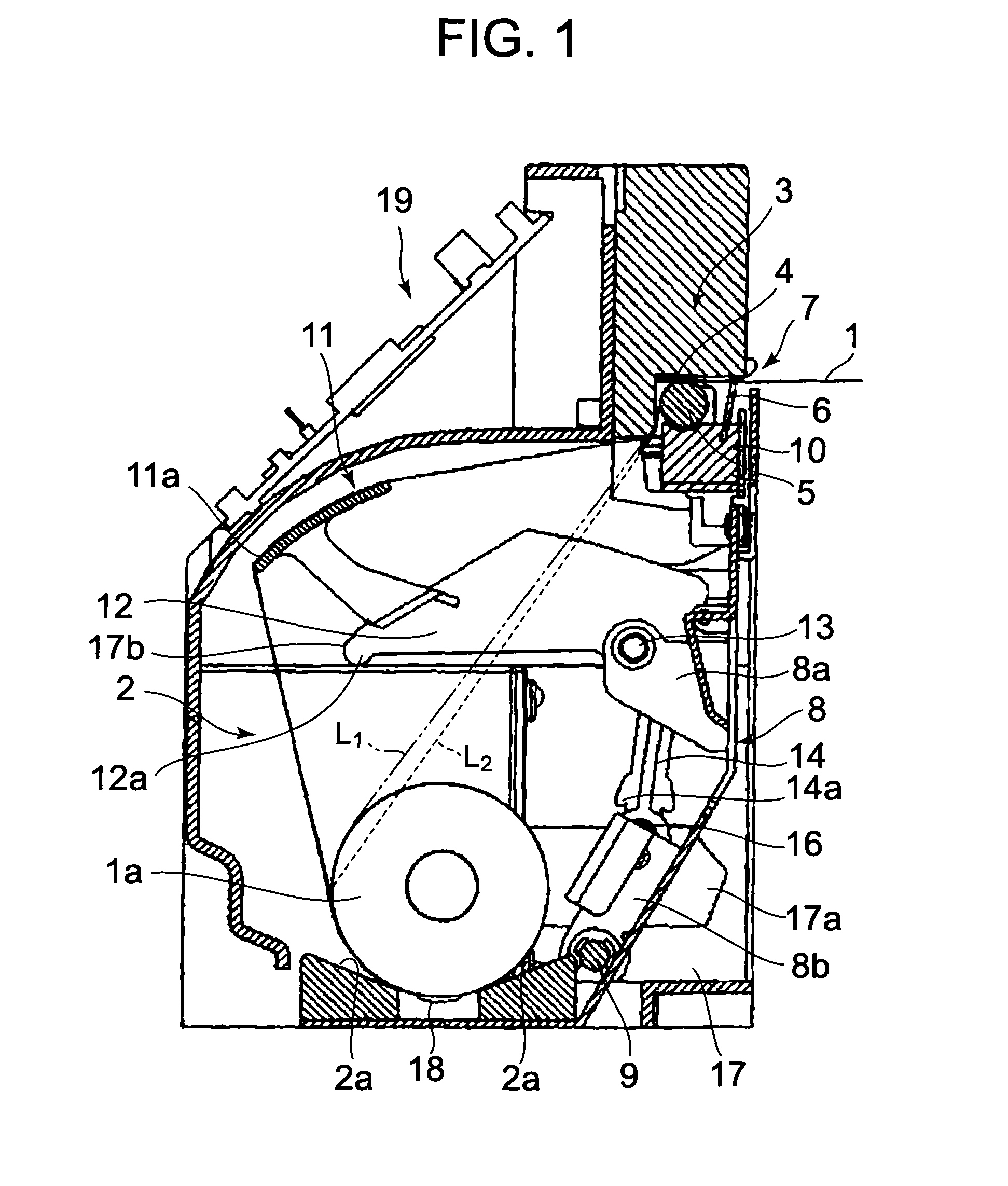
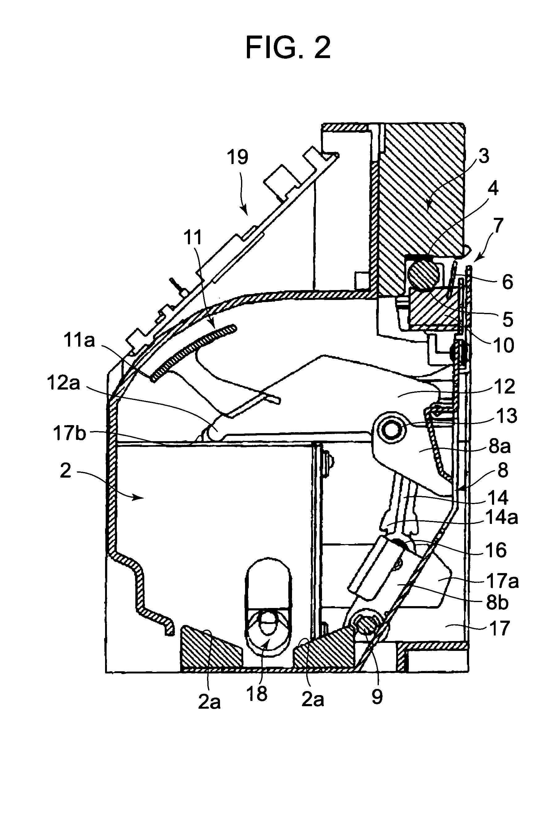
[0083]Next, with reference to FIGS. 13 to 18A-18C, another embodiment of the present invention will be described. FIGS. 13 and 14 each show an internal structure of a continuous sheet processing apparatus according to the present invention. FIG. 13 shows a state where the roll body 1a, in which the continuous sheet 1 is wound, is accommodated. FIG. 14 shows a state where the roll body 1a is not accommodated.

[0084]The continuous sheet processing apparatus according to this embodiment does not include the link arms 14, the shafts 15 and 16 for connecting the link arms 14, the cams 17a, and the guide grooves 17b. Further, the springs (not shown) biases the arms 12 toward the frame 17 side. That is, a direction of a bias force applied to the arms 12 by the springs is substantially opposite to that of the first embodiment described above. Other constructions are the same as those of the first embodiment shown in FIGS. 1 and 2, so descriptions thereof will be omitted.

[0085]In this embodim...

first embodiment

[0090]In this embodiment as well, the same operational effect as that of the first embodiment described above is obtained. Note that the guide plate 11 and the arms 12 have to be manually moved, so the operation becomes a little complicated, but at the same time, the need of the link arms 14 and the cams 17a is eliminated. As a result, it is possible to simplify the structure.

[0091]In the two embodiments described above, the guide plate 14 is attached to the cover 8 through the arms 12. However, there may be employed a structure in which the guide plate 14 is pivotally attached to the frame 17 through the arms 12 or another member. In this case, it is possible to more easily realize the structure in which the guide plate 11 and the arms 12 are moved manually in the same manner as that of the second embodiment of the present invention than the structure in which the guide plate 11 and the arms 12 automatically move together with the opening and closing of the cover 8 in the same mann...


PUM


Abstract

A continuous sheet processing apparatus has a frame, a roll body accommodating portion disposed inside of the frame for accommodating a roll body formed of a wound continuous sheet, and a cover mounted for undergoing pivotal movement between open and closed positions relative to the frame so as to allow the insertion of the wound continuous sheet into the roll body accommodating portion in the open position of the cover. A processing portion has a processing head and a platen roller confronting the processing head. The processing head performs a processing operation with respect to the continuous sheet drawn out from the roll body accommodating portion in a state in which the cover is in the closed position. The platen roller transports the continuous sheet in a state in which the cover is in the closed position.

Description

BACKGROUND OF THE INVENTION[0001]1. Field of the Invention[0002]The present invention relates to a continuous sheet processing apparatus for performing a processing such as printing or thermal activation with respect to a continuous sheet, and a method of setting a roll body in the continuous sheet processing apparatus.[0003]2. Description of the Related Art[0004]Hitherto, there is commonly known a continuous sheet processing apparatus, in which a continuous sheet is successively drawn but from a roll body to perform a processing such as printing or thermal activation with respect to the continuous sheet which is drawn out and a portion on which the processing is performed is cut off, thereby obtaining cutform paper.[0005]As a method of holding the roll body in the continuous sheet processing apparatus as described above, as disclosed in Patent Document 1, there is available a method in which a central shaft (roll shaft) is inserted into a central hole of a roll body and end portion...

Claims


Application Information

Patent Timeline
Patent Type & Authority Patents(United States)
IPC IPC(8): B65H16/10
CPCB41J2/32B41J15/042B41J15/046B65H5/06
Inventor TAKEUCHI, KIYOKAZU
Owner SEIKO INSTR INC
Why Eureka
Try Eureka