
Helix turbine system and energy production means

a technology of helix turbines and energy production means, which is applied in the direction of wind motors with parallel air flow, wind motors with perpendicular air flow, liquid fuel engine components, etc., can solve the problems of no prior art design or solution to improve the omnidirection savonius turbine type, and achieve the effect of increasing efficiency and greater ability to capture kinetic energy

Inactive Publication Date: 2011-07-12
BURRELL IV JAMES W
View PDF29 Cites 10 Cited by
  • Summary
  • Abstract
  • Description
  • Claims
  • Application Information

AI Technical Summary

Benefits of technology

"The present invention is a helix turbine system that improves the conversion of kinetic energy from moving fluids into rotational mechanical energy, resulting in increased rotations per minute. The system includes a circular disk, a conical or dome shaped shroud or housing, a hollow circular baseplate, and two counter rotating helical turbines. The system also uses aerodynamic fluid diverters and concentrators to increase the rotational speed of the turbine. The invention can be used in various applications such as generating electricity from wind or fluid flow. The technical effects of the invention include increased energy conversion efficiency, faster rotational speeds, and improved performance in various wind and fluid flow conditions."

Problems solved by technology

None of the prior art designs or solutions to improve the omnidirection Savonius type turbine, omnidirection helix turbine, low pressure turbine or any prior art turbine greatly improves the efficiency of harnessing the kinetic energy from moving fluids, extracting the most mechanical energy from a spinning turbine and converting the rotary motion into electricity.

Method used


Image

  • Helix turbine system and energy production means
  • Helix turbine system and energy production means
  • Helix turbine system and energy production means

Examples


Embodiment Construction

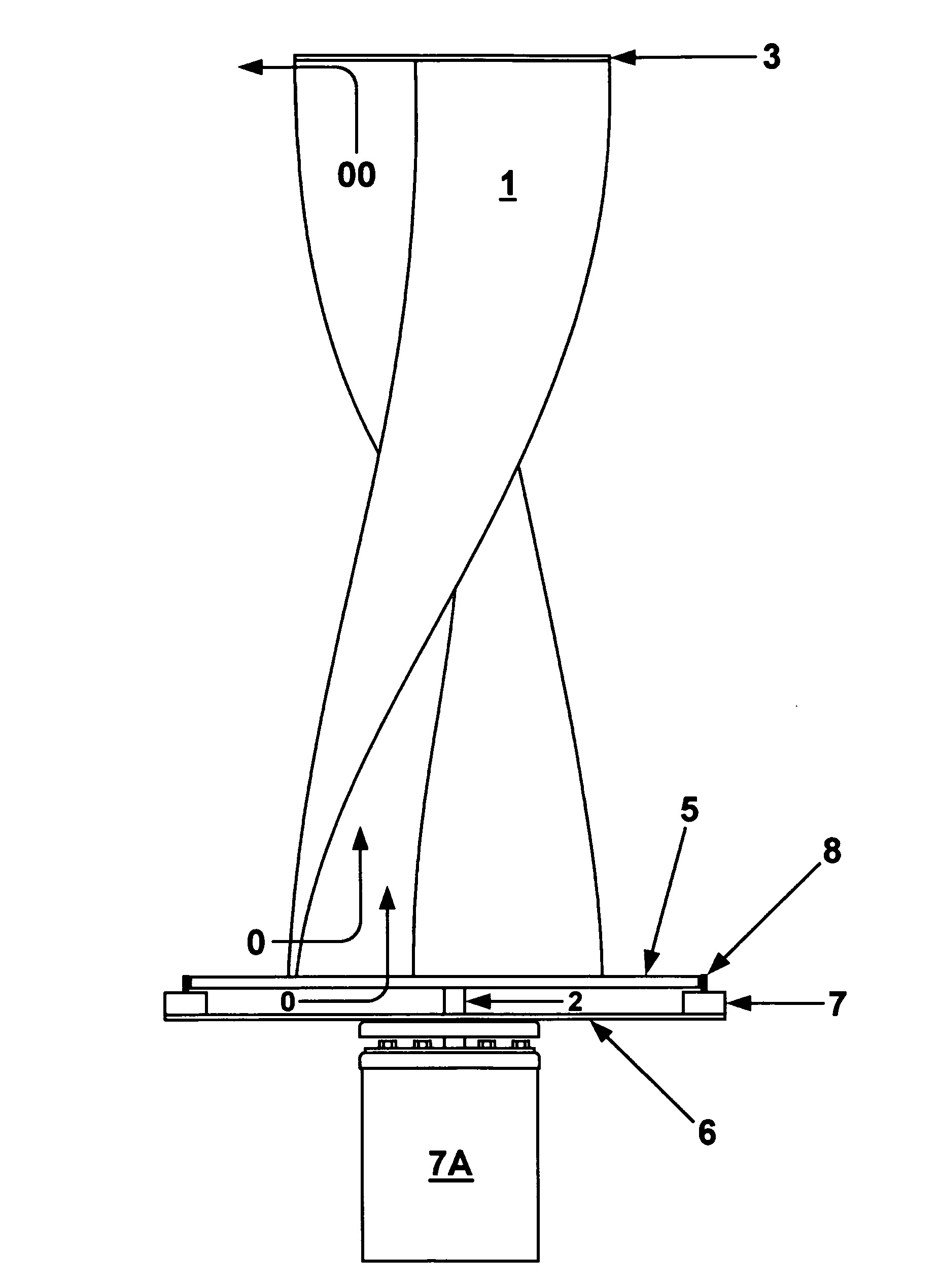
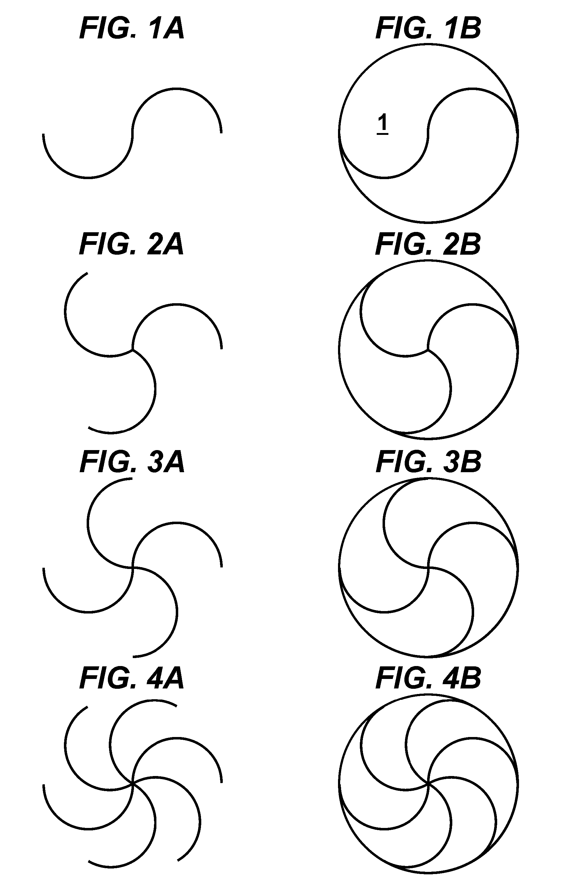
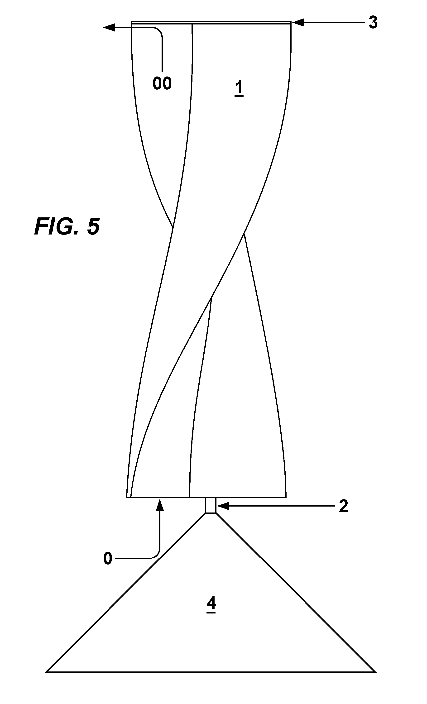
[0080]According to the present invention, the foregoing and other objects and advantages are attained by providing a turbine assembly and helical turbine system with a multitude of improvements for extracting the most kinetic energy from moving fluids while obtaining the maximum amount of mechanical rotational energy from a spinning turbine. In order to more fully understand the present invention, during the course of this description, the turbine assembly, helical turbine system, energy production method and preferred embodiments, will be labeled and explained to easily identify like elements according to the different embodiments which illustrate the presently disclosed invention. The scope of the invention is best defined by the appended claims and the description provided herein. Additional objects of the present invention will become apparent as the description proceeds.

[0081]The invention disclosed in the present patent application preferably uses two or more preferably axiall...


PUM


Abstract

A helical turbine with a circular member attached to one end for redirecting axially flowing fluid into perpendicularly flowing fluid. A fluid diverter for redirecting substantially perpendicular flowing fluid into axially flowing fluid. A hollow circular member attached to an opposite end of the turbine allowing substantially axial flowing fluid into one end of turbine. A drive shaft of at least one generator is in continuous contact with the peripheral edge of the solid or hollow circular member producing faster rpm. A turbine assembly mounted on a rooftop utilizing accelerated wind. Fluid diverters increasing fluid flow into the helical turbine's receding blades. A fluid diverter preventing fluid from hitting turbine's oncoming blades. A tail section for maintaining optimal direction into oncoming fluid. Two counter rotating turbines where the attached circular member's edges are in continuous contact. Multiple turbine body assemblies, using different combinations of disclosed elements, produce multiple preferred embodiments.

Description

FIELD OF THE INVENTION[0001]The present invention relates to multiple designs, arrangements and uses of omnidirection Savonius type turbines, omnidirection helix turbines and low pressure turbines for extracting and converting the kinetic energy from moving fluids (wind and water) into mechanical rotary energy for the preferred production of electricity.DESCRIPTION OF THE PRIOR ART[0002]There are many prior art disclosures and uses of omnidirection Savonius type turbines, omnidirection helix turbines and low pressure turbines to harness the kinetic energy from moving fluids, mostly the wind. Savonius' first patent, U.S. Pat. No. 1,697,574, was a vertical two bladed rotor designed to be powered by wind or flowing water. Since then, many attempts to use or modify the Savonius type turbine invention have been made. The most notable examples are found in U.S. Pat. Nos. 1,766,765, 4,293,274, 4,715,776, 4,784,568, 4,830,570, 4,838,757, 5,391,926, 5,494,407, 5,852,331, 6,283,711, 6,428,275...

Claims


Application Information

Patent Timeline
Patent Type & Authority Patents(United States)
IPC IPC(8): F03D3/06
CPCF03D3/049F03D3/061F05B2240/213F05B2250/25Y02B10/30Y02B10/70Y02E10/74F03D3/02F03D9/25F03D15/10F03D80/70
Inventor BURRELL, IV, JAMES W.
Owner BURRELL IV JAMES W
Learn More