Composite discharge electrode

a discharge electrode and composite technology, applied in the direction of discharge tube/lamp details, discharge tube main electrodes, discharge tubes/lamp details, etc., can solve the problems of affecting the charging efficiency of discharge electrodes. , to achieve the effect of improving the charging characteristic and collection efficiency, reducing the cost and weigh

Inactive Publication Date: 2011-07-12
OHIO UNIV
View PDF20 Cites 27 Cited by
  • Summary
  • Abstract
  • Description
  • Claims
  • Application Information

AI Technical Summary

Benefits of technology

The object of the invention is to replace part or all of the conventional charging electrode system with new materials focusing on carbon fibers, ceramic fibers (e.g., silicon carbide, and glass fibers), and metal fibers. The disadvantages of the state-of-the-art that are overcome by the invention include a reduction in cost and weight, and an improvement in charging characteristics and collection efficiency.
Polymer composites can be designed to be conductive and strong enough to function as a discharge electrode. The invention uses materials, such as plastic or glass and carbon fiber reinforced composites, for the discharge electrode support structure to reduce weight, eliminate corrosion and reduce cost. The discharge electrodes are commonly mounted on a support structure, such as a rod. Additionally, metal, conducting fiber mat or fiber reinforced composites are used for the electrodes. Preferably, the electrode is made of a mat or a composite that includes carbon fiber or carbon nanofiber, and has a simple or conventional discharge electrode shape, such as a star or circular disk shape.
The flexibility of fibers make them amenable to forming of the electrodes into different shapes and orientations that can produce a more uniform corona and reduce sneakage. It is also contemplated to sandwich carbon fiber or other conducting fiber mat between two discs, and it is alternatively contemplated to bond fiber or mat to a disc so that the advantages of the carbon fiber mat can be combined with the stiffness of a solid disc without forming a composite matrix around the fiber mat. The discs around the mat can be metal, polymer or plastic. In another contemplated embodiment, a woven carbon fabric is partially reinforced by a polymer.
It was expected that the use of composites, which have lower conductivity than metal, would result in the same or lower collection efficiency and current flow. Instead, the composites worked significantly better, as shown by the experimental data. The corona current and the collection efficiencies were observed to be much better with the invention than the prior art.
Although the small fibers could be damaged due to sparkover, the deposition of metal on the fiber tips would avoid this problem. Additionally, it is contemplated to mold metal needles or filaments into the disks or through the support rod in alternative embodiments. Instead of using conventional carbon fibers, it is possible to use carbon nanofibers or nanotubes which are much smaller in diameter. Metal or ceramic fibers, whiskers, or nanowires can also be used. Such materials can be placed within a composite electrode so that there are many tips of conductive fibers evenly distributed around the electrode, thereby producing a uniform corona.

Problems solved by technology

Precipitators can fail once a very heavy buildup of waste material forms on the plates.
The buildup can block airflow or bridge across insulating gaps and short out the high-voltage power supply.
The sharp spikes of the charging electrodes are also typically made of an expensive alloy to avoid or mitigate corrosion in the harsh environments in which such electrodes are used.
The entire discharge electrode, including the rod, is commonly made of the alloy, causing the electrodes to be expensive and heavy, thereby requiring strong support structures.
Polymers are inexpensive, light and corrosion-resistant, but they do not conduct electricity, and they have poor tensile / flexural strength.

Method used


Image

  • Composite discharge electrode
  • Composite discharge electrode
  • Composite discharge electrode

Examples


Embodiment Construction

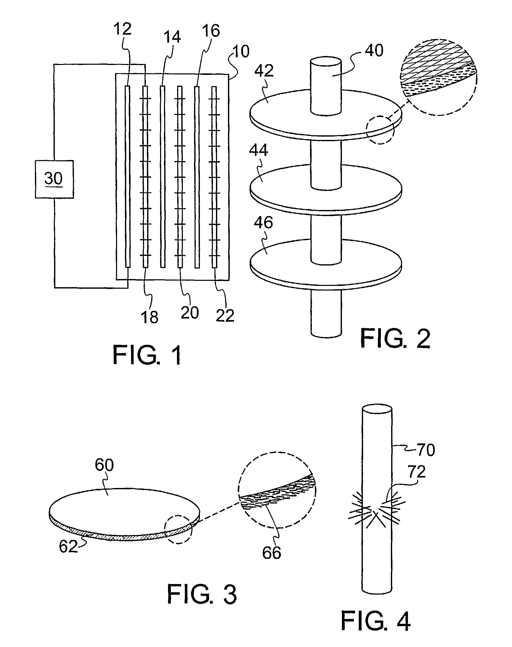
In FIG. 1 an ESP is shown schematically having a housing 10, which can be a flue gas chimney, a plurality of planar collection electrode plates 12, 14 and 16, and a plurality of discharge electrodes 18, 20 and 22. The discharge electrodes and collection plates are supported by a frame (not shown), which can be integral with the housing 10, and are electrically connected to a power supply 30. Gases, such as flue gases containing flyash particles, flow through the housing 10 in a flow path across the plates 12-16 and the discharge electrodes 18-22, which function according to the principles discussed herein, and with much improved performance over the prior art due to the improvements to the discharge electrodes 18-22.

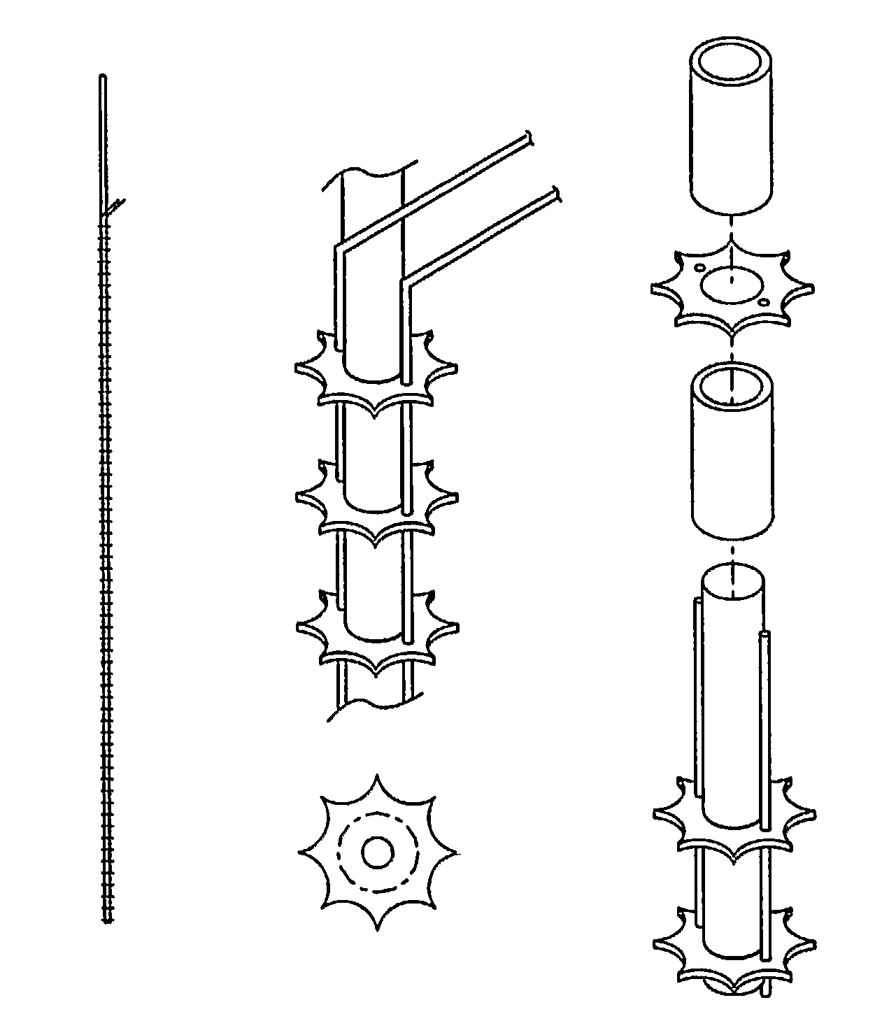
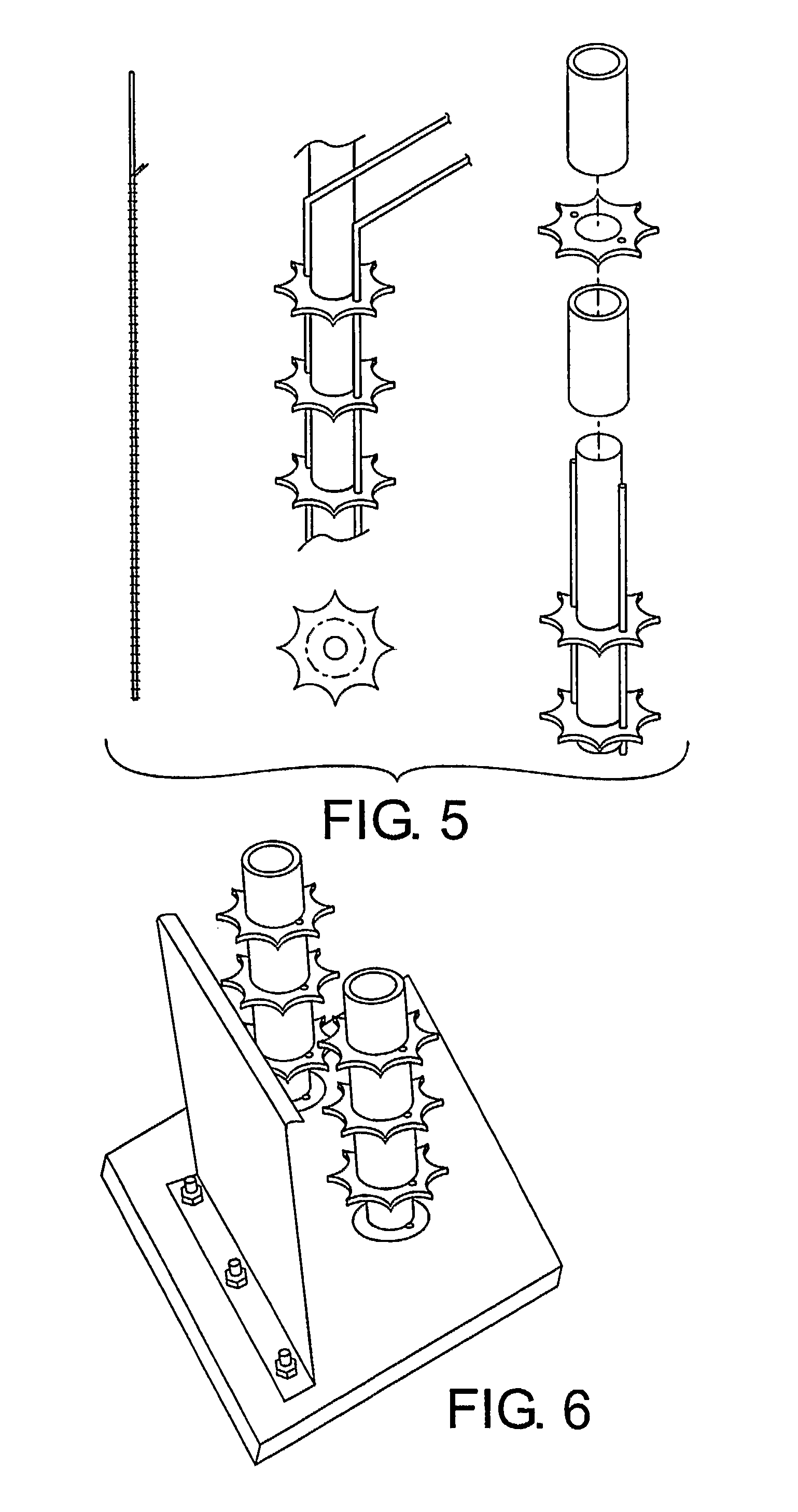
Each discharge electrode system, an example of which is shown schematically in FIG. 2, has a supporting rod 40 that supports a plurality of fiber composite discharge electrode plates, such as the circular disks 42, 44 and 46, spaced along the length of the rod. The rod 4...


PUM


Abstract

The invention is a discharge electrode in an electrostatic precipitator having a power supply connected to at least one collection electrode and a flow of gas across the collection electrode. The discharge electrode has a plurality of conductive fibers electrically connected to the power supply and fiber tips exposed to the flow of gas. The fiber tips preferably extend from a composite in which the fibers reinforce a matrix material, but alternatively can be a large number of filaments extending from a composite rod.

Description

BACKGROUND OF THE INVENTIONThe invention relates generally to electrostatic precipitators (ESPs), and more particularly to a discharge electrode for an ESP.DESCRIPTION OF THE RELATED ARTCharging electrodes are critical components used in electrostatic precipitators (ESPs), which are devices used to collect particles from gas streams, such as the streams from electric power plants burning coal. An example of such a device is shown in U.S. Pat. No. 6,231,643 to Pasic, et al., which is incorporated herein by reference.The most basic ESP contains a row of wires followed by a stack of spaced, planar metal plates. A high-voltage power supply transfers electrons from the plates to the wires, developing a negative charge of thousand of volts on the wires relative to the collection plates. In a typical ESP, the collection plates are grounded, but it is possible to reverse the polarity.The gas flows through the spaces between the wires, and then passes through the rows of plates. The gases ar...

Claims


Application Information

Patent Timeline
Patent Type & Authority Patents(United States)
IPC IPC(8): B03C3/41
CPCB03C3/41B03C3/47B03C3/62B03C3/64B03C2201/10
Inventor ALAM, M. KHAIRUL
Owner OHIO UNIV
Why Eureka
Try Eureka