Multi-phase interferometer

a multi-phase interferometer and optical sensing technology, applied in the direction of speed/acceleration/shock measurement, measurement devices, instruments, etc., can solve the problems of high environmental impact sensitivity of optical detection methods, especially interferometers, loss of signal intensity, signal distortion,

Inactive Publication Date: 2011-07-12
TECHNION RES & DEV FOUND LTD
View PDF1 Cites 1 Cited by
  • Summary
  • Abstract
  • Description
  • Claims
  • Application Information

AI Technical Summary

Benefits of technology

[0008]In accordance with the present invention there is provided an optical perturbation sensing system, comprising a probing beam incident on a medium with perturbations, a sensing beam redirected from said medium and incident onto the surface of a photodetector, a reference beam directed onto the photodetector surface to form, with the sensing beam, an interference pattern on the photodetector surface, a phase patterner imposing at least two phase regions across its section, to generate different phases in different regions of said interference pattern, an array of photodetector elements, to detect each phase region of the interference pattern independently, and a constructive combiner for constructively combining detected signals from said elements, to form a stronger detected signal with reduced intensity noise, reduced background noise, and reduced sensitivity to phase drifts.
[0009]The invention further provides an optical perturbation sensing system, comprising a multiplexed probing beam set incident on a medium with perturbations, a multiplexed sensing beam set redirected from said medium and incident on a surface area of a photodetector, a multiplexed reference beam set directed onto a corresponding set of photodetector elements to form with said multiplexed sensing beam set an interference pattern on each the photodetector element surfaces, a set of phase shifters to shift the relative phase of each interference pattern on each of the photodetector elements, and a constructive combiner for constructively combining the detected signals from said photodetector elements, to form stronger detected signal with reduced intensity noise and reduced background noise and reduced sensitivity to phase drifts.
[0010]The invention still further provides a method for detection of perturbations in a medium, comprising generating a probing beam, incidenting said beam onto a medium, sensing the beam reflecting from said medium and incidenting it on a photodetector, combining said reflected beam with a reference beam on a photodetector, segmenting said photodetector into elements, introducing a phase patterner to pattern the phase of the interference pattern and generate a different interferometric phase on each said photodetector element, independently detecting signals from each element, subtracting pairs of said detected signals, squaring the subtracted signal squares, and summing up said squared signals to an overall stronger detection signal, with reduced intensity noise, reduced background noise and reduced sensitivity to spurious phase shifts.
[0011]The invention yet further provides a method for detection of perturbations in a medium, comprising generating a multiplexed probing beam set, incidenting said beam set onto a medium, sensing the beam set reflecting from said medium and incidenting each beam in the set on a photodetector, combining each said reflected beam with a reference beam from the multiplexed reference beam set on a photodetector, introducing phase shifters to shift the phase of each interference pattern and to generate a different interferometric phase on each photodetector, detecting signals from each photodetector element, subtracting pairs of said detected signals, squaring the subtracted signal squares, and summing up said squared signals to an overall stronger detection signal, with reduced intensity noise, reduced background noise and reduced sensitivity to spurious phase shifts.

Problems solved by technology

Optical detection methods, and especially interferometers, however, suffer from high sensitivity to environmental effects, such as instability and vibrations in the test arrangement, and temperature variations.
The environmental instabilities lead to drift of the interferometer from its optimal operation point, which lead to loss of signal intensity, and signal distortion.
These solutions require optical frequency modulation and specialized optics, making them, as other state of the art solutions, relatively bulky and expensive.
The former method is impractical due to alignment difficulties: the substantial difference in the optical paths of the reference beam portions; and the introduction of vibration noise through the difficulty to stabilize the relative location of the phase-shifting plate and the reference beam.
The latter method is complex and also suffers from the need for high precision alignment as well as stability requirements.

Method used


Image

  • Multi-phase interferometer
  • Multi-phase interferometer
  • Multi-phase interferometer

Examples


Embodiment Construction

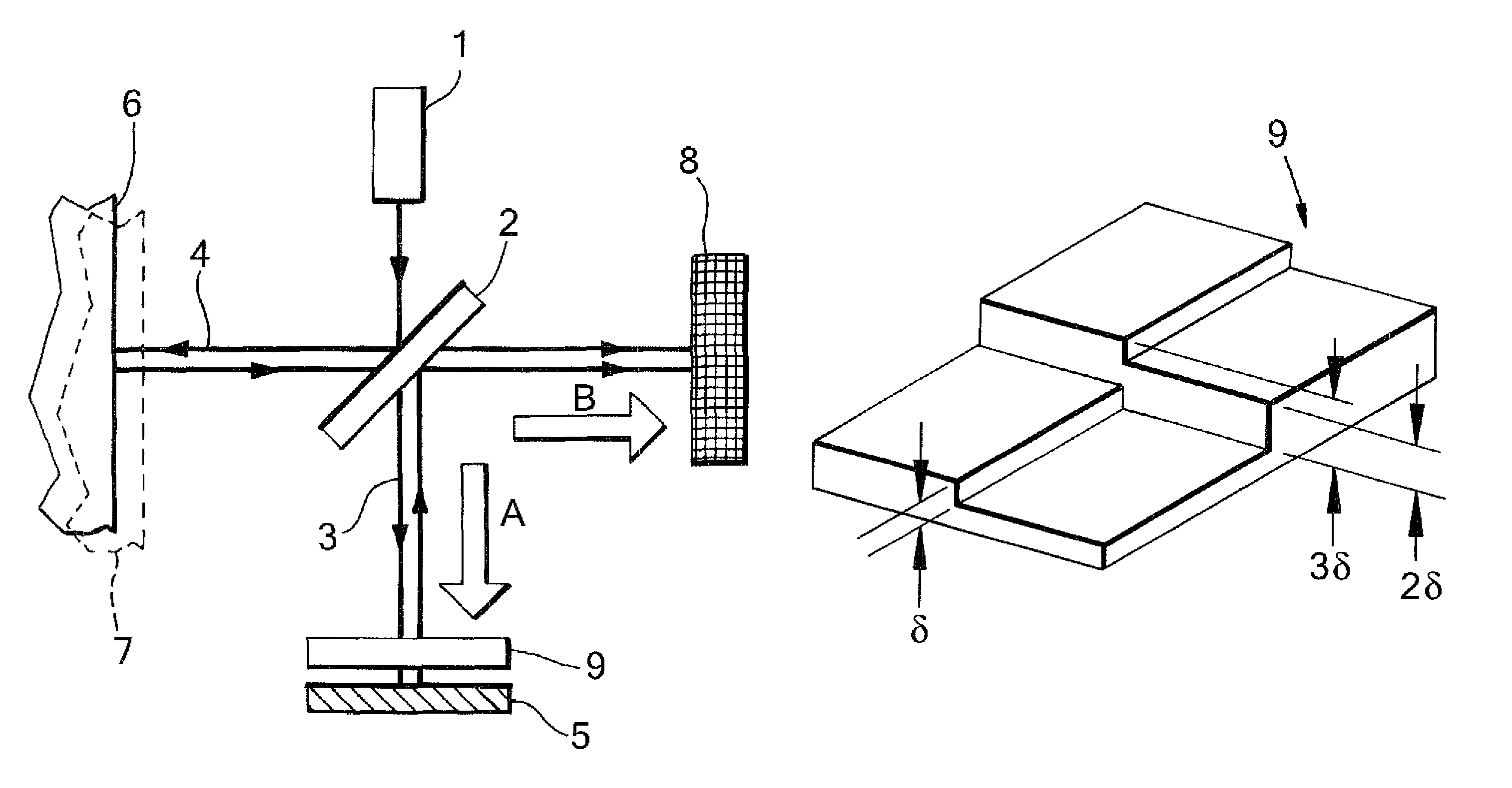
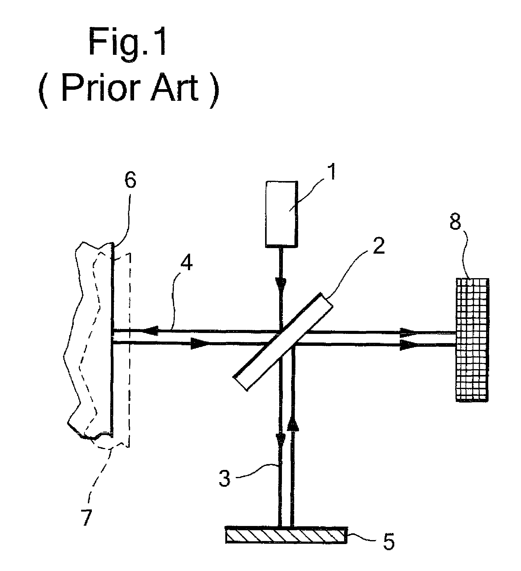
[0032]FIG. 1 schematically illustrates a Michelson optical interferometer. This configuration is well-known and sufficiently generic to represent other inter-ferometric configurations, such as the Mach-Zehnder, and the following description applies to other interferometric arrangements, which are not detailed here in the interest of brevity. In particular the following description addresses interferometric configurations where the reference beam is reflected back on itself (as in FIG. 1), and configurations where the reference beam is directed to travel only in one attitude over its path (as for example is the case in the Mach-Zehnder Interferometer). Also in the interest of brevity, the following description considers, by way of example, sensing surface perturbations; the description applies to any other interferometric detection of phase perturbations, both in a the surface reflected mode, as well as in a transmission through a medium.

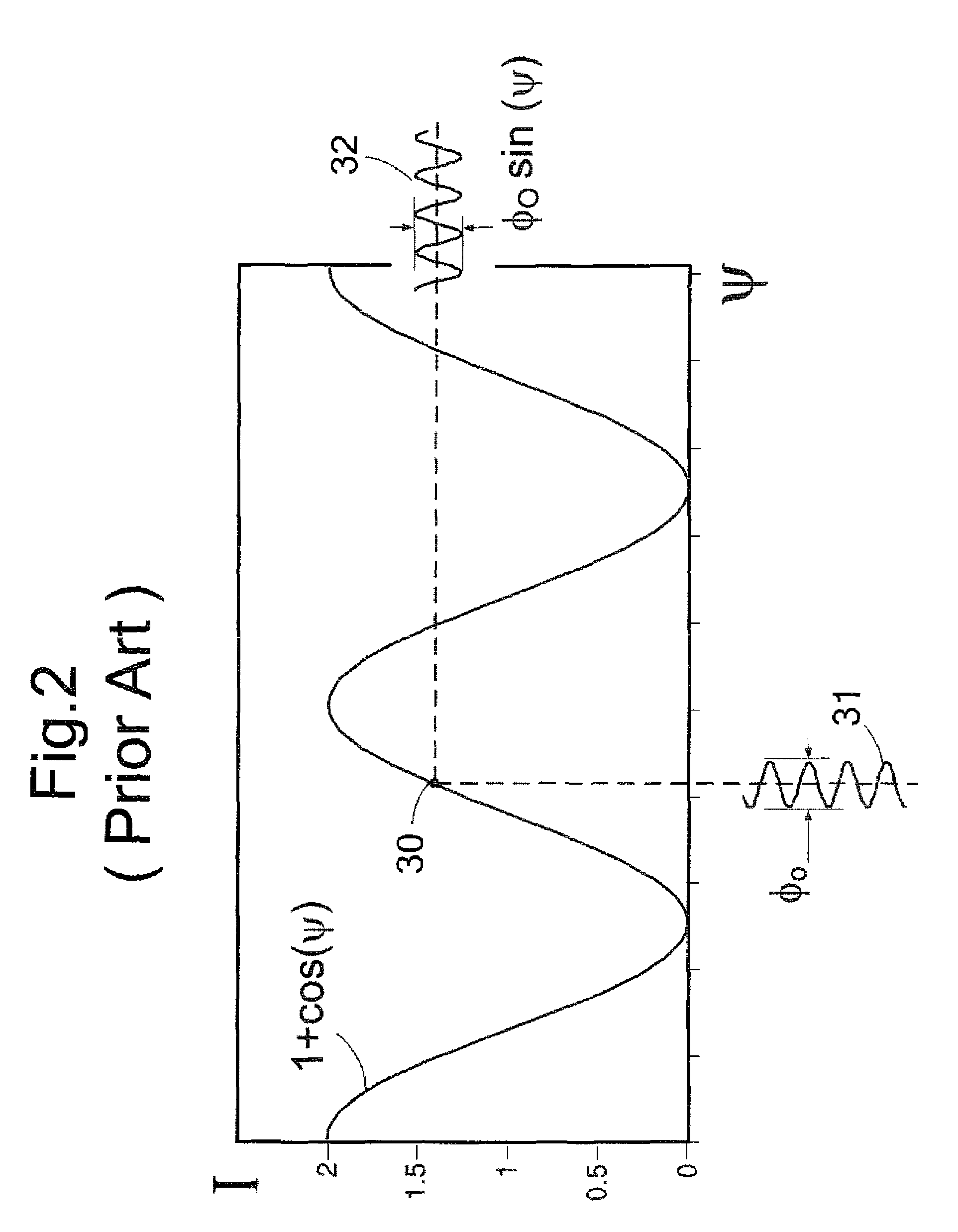
[0033]In a generic prior-art interferometer (F...


PUM


Abstract

An optical perturbation sensing system includes a probing beam incident on a medium with perturbations and a sensing beam redirected from the medium and incident on a surface area of a photodetector. A reference beam directed onto the photodetector surface forms, with the sensing beam, an interference pattern on the photodetector surface and a phase patterner with at least two phase regions across its section, generates different phases in different regions of the interference pattern. An array of photodetector elements detects each phase region of the interference pattern and a constructive combiner subtract pairs of the detected signals, squares the subtracted signal squares, and sums the squared signals to form a stronger detected signal with reduced intensity noise, reduced background noise, and reduced sensitivity to phase drifts.

Description

RELATED APPLICATION[0001]This application is a Continuation-In-Part application of PCT / IL07 / 001389 filed Nov. 13, 2007.FIELD OF THE INVENTION[0002]The present invention relates to a system and a method for interferometric optical sensing of small disturbances, and in particular, to interferometric optical sensing of a surface.[0003]The invention can be implemented to advantage in a variety of optical sensing of vibrations, acoustic waves and ultrasound as well as other physical parameters which affect the phase of an optical probing beam. The present invention alleviates two major practical difficulties with implementation of interferometers in an uncontrolled environment: the drift in the sensitive “work-point” of the interferometer due to instabilities in the environment, and the presence of amplitude noise in the light source and the environment. Unlike state of the art methods for stabilizing interferometers, the present invention offers a low cost and compact implementation.BAC...

Claims


Application Information

Patent Timeline
Patent Type & Authority Patents(United States)
IPC IPC(8): G01B9/02
CPCG01H9/00G01B9/0201G01B9/02076G01B9/02027G01B2290/70
Inventor AHARONI, AVRAHAM
Owner TECHNION RES & DEV FOUND LTD
Why Eureka
Try Eureka