
Test system for conducting parallel bit test

a test system and parallel bit technology, applied in error detection/correction, instruments, computing, etc., can solve the problems of reducing the possibility of detecting defects in memory modules and difficult to detect defects in memory modules, so as to reduce the possibility of detecting defects

Inactive Publication Date: 2011-07-12
SAMSUNG ELECTRONICS CO LTD
View PDF8 Cites 4 Cited by
  • Summary
  • Abstract
  • Description
  • Claims
  • Application Information

AI Technical Summary

Benefits of technology

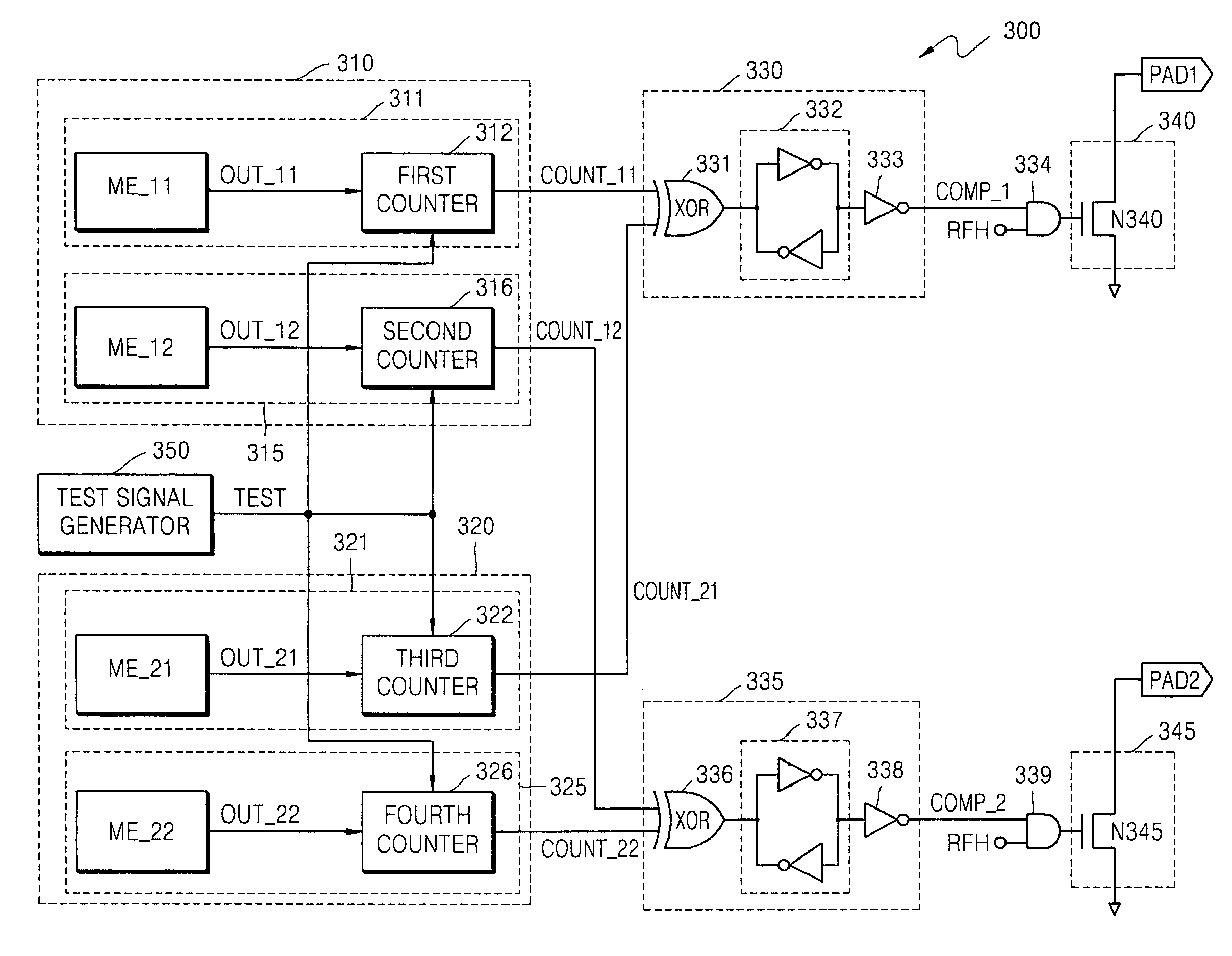
The present invention provides a test system for detecting defects in multiple memory modules when conducting a parallel bit test. The test system includes counters associated with each memory module, which generate a count signal based on the number of data bits with a reference logic state among the output data signals. A determining device outputs a comparison signal based on the count signals, indicating whether there is a defect in the memory modules. A controller selectively disables outputting the data output signals based on the comparison signal. The test system can reduce the likelihood of errors in detecting defects in multiple memory modules.

Problems solved by technology

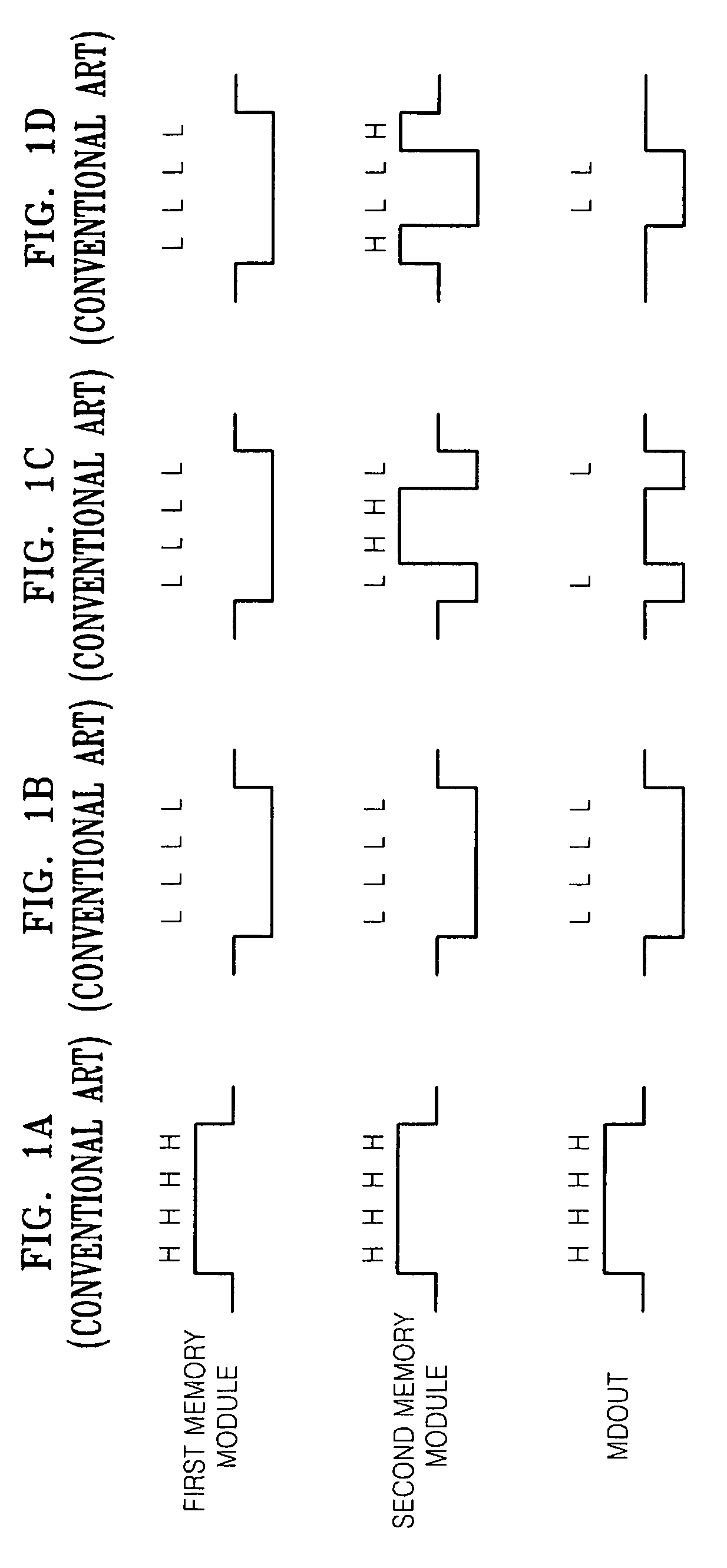
However, the possibility of detecting defects of the memory modules is decreased when each of the memory modules outputs data in different states as shown in FIGS. 1C and 1D because the MDOUT has unstable state.
For example, if the first memory module outputs data in a logic low state and the second memory module outputs data in a logic high state or the first memory module outputs data in a logic high state and the second memory module outputs data in a logic low state, the data outputted from each of the memory modules are merged to have an intermediate voltage level between the logic high and logic low values, and thus, making it difficult to detect defects in the memory modules.

Method used


Image

  • Test system for conducting parallel bit test
  • Test system for conducting parallel bit test
  • Test system for conducting parallel bit test

Examples


Embodiment Construction

[0037]Detailed example embodiments are disclosed herein. However, specific structural and functional details disclosed herein are merely representative for purposes of describing example embodiments. Example embodiments may, however, be embodied in many alternate forms and should not be construed as limited to only the embodiments set forth herein.

[0038]Accordingly, while example embodiments are capable of various modifications and alternative forms, embodiments thereof are shown by way of example in the drawings and will herein be described in detail. It should be understood, however, that there is no intent to limit example embodiments to the particular forms disclosed, but to the contrary, example embodiments are to cover all modifications, equivalents, and alternatives falling within the scope of example embodiments. Like numbers refer to like elements throughout the description of the figures.

[0039]It will be understood that, although the terms first, second, etc. may be used h...


PUM


Abstract

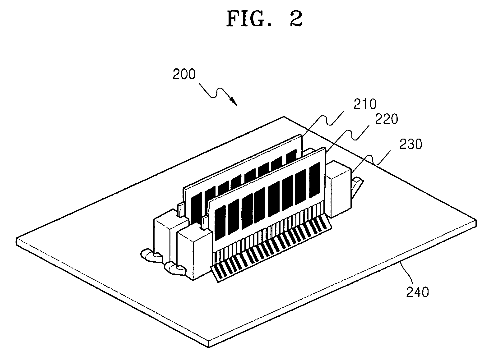
Provided is a test system conducting a parallel bit test. The test system, conducting a parallel bit test on a plurality of memory modules mounted on a socket, comprises a plurality of counters and a comparator. Each of the counters counts the number of data output signals in the same logic state, among the data output signals outputted from each memory of the memory modules, and outputs a count signal. The comparator compares the count signal outputted from each of the counters and outputs a comparison signal corresponding to a defect of the memory modules. According to the test system, defects in a memory module can be accurately detected and a possibility of an error in the detection can be reduced when a plurality of memory modules are tested, as compared to conventional test systems.

Description

FOREIGN PRIORITY STATEMENT[0001]This application claims priority under 35 U.S.C. §119 to Korean Patent Application No. 10-2008-0021566, filed on Mar. 7, 2008, in the Korean Intellectual Property Office (KIPO), the entire contents of which are incorporated herein in by reference.BACKGROUND[0002]1. Field of the Invention[0003]The present invention relates to a memory module test, and more particularly, a test system for conducting parallel bit tests on a plurality of memory modules.[0004]2. Description of the Related Art[0005]A manufacturing process of semiconductor memory devices such as dynamic random access memory (DRAM) includes circuit design, various fabrication processes, and various test steps. The various test steps may include a wafer test, a package test and a module test and the like. Generally, a parallel bit test has been used to reduce test time in each test step. A parallel bit test is a test method that can find a memory having defects by writing the same data into a ...

Claims


Application Information

Patent Timeline
Patent Type & Authority Patents(United States)
IPC IPC(8): G11C29/00
CPCG11C29/26G11C5/04G11C2029/2602G11C29/10G11C29/20G11C2029/3602
Inventor KIM, BYOUNG-SULLEE, SEUNG-HEELEE, JUNG-KUKCHOI, HEE-JOO
Owner SAMSUNG ELECTRONICS CO LTD
Learn More