
Light sources utilizing segmented LEDs to compensate for manufacturing variations in the light output of individual segmented LEDs

a technology of led light source and led light source, which is applied in the direction of electric variable regulation, process and machine control, instruments, etc., can solve the problems of limited power level at which an led is the lifetime of the led is also reduced by operation, and the single led light source is not capable of generating sufficient ligh

Inactive Publication Date: 2011-07-19
BX LED LLC
View PDF15 Cites 21 Cited by
  • Summary
  • Abstract
  • Description
  • Claims
  • Application Information

AI Technical Summary

Benefits of technology

"The present invention is a light source made up of multiple Segmented LEDs connected in parallel to a power bus and controlled by a controller. Each Segmented LED has a driving voltage that is greater than three times higher than a conventional LED. The number of Segmented LEDs can be adjusted to compensate for variations in light output caused by manufacturing processes. Additionally, the number of Segmented LEDs can be changed after assembly. The technical effects of this invention include improved control over the light output and flexibility in the number of LEDs used."

Problems solved by technology

Heat dissipation often places a limit on the power level at which an LED operates.
In addition, the lifetime of the LED is also decreased by operation at high currents.
Single LED light sources are not capable of generating sufficient light to replace conventional light sources for many applications.
This limit is imposed by the power dissipation and the electrical conversion efficiency of the LED material system.
Hence, to provide a higher intensity single LED source, larger area chips must be utilized; however, there is a limit to the size of a single LED chip that is imposed by the fabrication process used to make the LEDs.
As the chip size increases, the yield of chips decreases, and hence, the cost per LED increases faster than the increase in light output once the chip size increases beyond a predetermined size.
However, there are other considerations such as the cost and reliability of the light source that must be taken into consideration in addition to the power-to-light conversion efficiency.
From a reliability point of view, a single series connected string of LEDs is the poorest option.
In general, LEDs are more likely to fail by forming an open circuit than a short circuit.
For example, a wire-bond that connects a pad in the LED to external circuitry can fail.
Hence, a single LED failure in the series-connected string leads to the catastrophic failure of the light source.
Unfortunately, such an arrangement is inefficient from the point of view of the power supply efficiency and requires conductors that can handle very large currents without introducing significant transmission costs.
In general, the variation in light output among the LEDs is too great to meet the needs of the light source manufacturers without some sorting of the LEDs to provide LEDs with less variability.
The sorting process adds to the costs of the light source.
In addition, many light sources cannot utilize LEDs that are not within a range of intensities that is less than the spread in intensities of the LEDs as manufactured.
As a result, there is less of a market for LEDs that are not in the range of interest, which increases the cost of the LEDs in the desired range and decreases the cost of the LEDs that are outside that range.
However, the remaining LEDs are overdriven by 20 percent since these LEDs must pass the current that no longer passes through the open circuited component light source.
Unfortunately, this strategy does not eliminate the need for utilizing only a subset of the production run of LEDs for any given final light source.

Method used


Image

  • Light sources utilizing segmented LEDs to compensate for manufacturing variations in the light output of individual segmented LEDs
  • Light sources utilizing segmented LEDs to compensate for manufacturing variations in the light output of individual segmented LEDs
  • Light sources utilizing segmented LEDs to compensate for manufacturing variations in the light output of individual segmented LEDs

Examples


Embodiment Construction

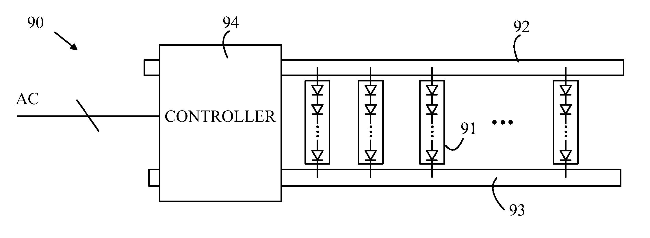
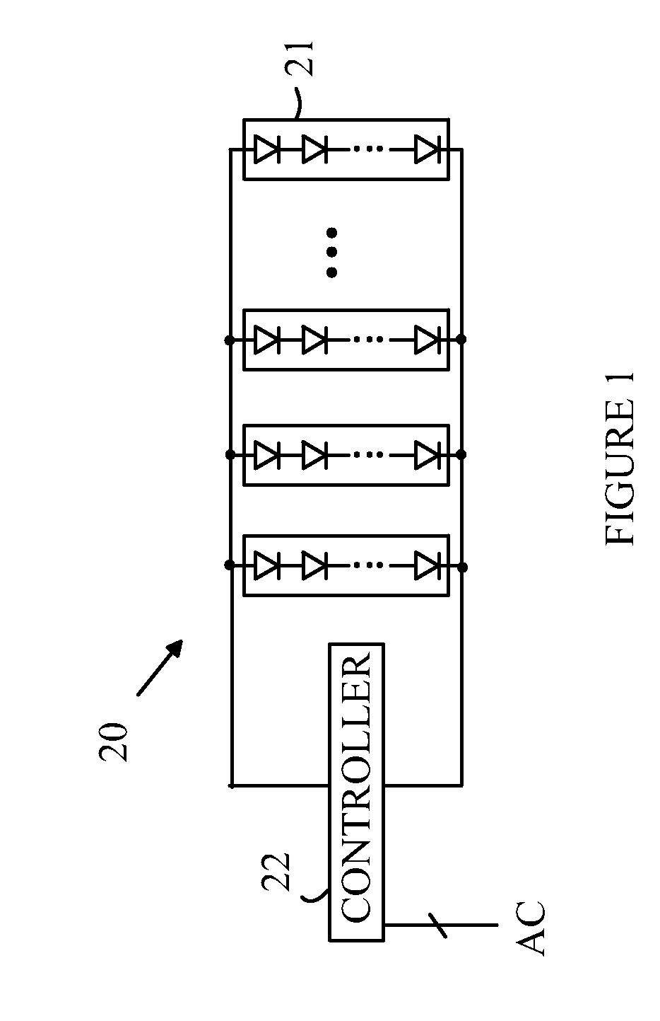
[0022]The manner in which the present invention provides its advantages can be more easily understood with reference to FIG. 1, which illustrates one embodiment of a light source according to the present invention. Light source 20 includes a plurality of Segmented LEDs 21 that are connected in parallel to a DC constant current source. The average current through each Segmented LED is set by controller 22, which includes an AC to DC power converter.

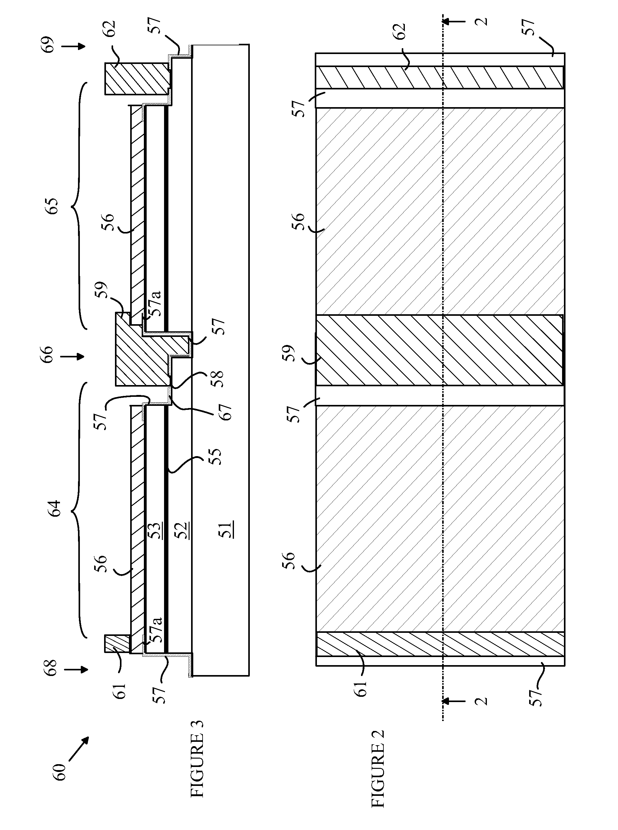
[0023]Segmented LEDs are discussed in detail in co-pending U.S. patent application Ser. No. 12 / 208,502, filed Sep. 11, 2008, which is hereby incorporated by reference. A detailed discussion of a Segmented LED will also be provided below. For the purposes of the present discussion, it is sufficient to note that each Segmented LED is defined to be a single LED die that is divided into N segments that are serially connected to one another, where N>1 and typically between 2 and 100. Each segment is, in effect, a small LED. The area of each Seg...


PUM


Abstract

A light source and method for making the same are disclosed. The light source includes a plurality of Segmented LEDs connected in parallel to a power bus and a controller. The power bus accepts a variable number of Segmented LEDs. The controller receives AC power and provides a power signal on the power bus. Each Segmented LED is characterized by a driving voltage that is greater than 3 times the driving voltage of a conventional LED fabricated in the same material system as the Segmented LED. The number of Segmented LEDs in the light source is chosen to compensate for variations in the light output of individual Segmented LEDs introduced by the manufacturing process. In another aspect of the invention, the number of Segmented LEDs connected to the power bus can be altered after the light source is assembled.

Description

BACKGROUND OF THE INVENTION[0001]Light emitting diodes (LEDs) are an important class of solid-state devices that convert electric energy to light. Improvements in these devices have resulted in their use in light fixtures designed to replace conventional incandescent and fluorescent light sources. The LEDs have significantly longer lifetimes and, in some cases, significantly higher efficiency for converting electric energy to light.[0002]For the purposes of this discussion, an LED can be viewed as having three layers, the active layer sandwiched between two other layers. The active layer emits light when holes and electrons from the outer layers combine in the active layer. The holes and electrons are generated by passing a current through the LED. The LED is powered through an electrode that overlies the top layer and a contact that provides an electrical connection to the bottom layer.[0003]The cost of LEDs and the power conversion efficiency are important factors in determining t...

Claims


Application Information

Patent Timeline
Patent Type & Authority Patents(United States)
IPC IPC(8): H05B41/36H05B44/00
CPCH01L27/153H05B33/0827H01L33/62H01L2924/0002H01L2924/00H05B45/46H01L25/0753H05B33/10H01L2933/0066H05B45/54H05B45/10H01L27/15H01L33/48H10K59/10H05B45/48H05B47/185
Inventor HASNAIN, GHULAMHU, SYN-YEMLESTER, STEVEN D.
Owner BX LED LLC
Learn More