Method and system for physical layer aggregation

a physical layer and aggregation technology, applied in the field of communication networks, can solve the problems of imposing limitations on the distribution of data among physical links associated with a single logical link, network architects may face a number of constraints, and the bandwidth of link pl may limit the data transfer rate between network devices a_ and b_,

Inactive Publication Date: 2011-07-26
AVAGO TECH INT SALES PTE LTD
View PDF1 Cites 21 Cited by
  • Summary
  • Abstract
  • Description
  • Claims
  • Application Information

AI Technical Summary

Problems solved by technology

The task of achieving increasing link speeds is one of the challenges in computer networking technology.
In pursing the goal of higher data rates, network architects may face a number of constraints.
Such higher, or “cutting edge”, data rates often require components, such as integrated circuit (IC) devices, and interconnect, such as category 6 (Cat6) or Cat7 cabling, which are more expensive than equivalent, more commonly used hardware that may not be capable of achieving the higher data rates.
Thus, economic considerations potentially represent one such constraint.
Various limitations dictate a speed at which components may operate, and a speed at which data may be transferred by the components and / or via interconnect.
However, the IEEE 802.3ad link aggregation may impose limitations on how data may be distributed among the physical links associated with a single logical link.
This limitation may be related to the method in which network devices communicate within the network.
One limitation in IEEE 802.3ad link aggregation is that packets containing data transmitted from a source network device (for example A_) to a destination network device (for example B_), associated with a given conversation (for example cid=1), may be required to be transmitted via a single physical link, PL1, even though the logical link, LL1, may comprise a group of physical links, PL1, PL2, PL3 and PL4, for example.
However, if the network devices A_ and B_ are engaged in a single conversation, for example the conversation cid=1, the data transfer rate between the network devices A_ and B_ may be limited by the bandwidth of link PL1.
One potential reason for this limitation is that the IEEE 802.3ad standard may impose temporal ordering restrictions on packets transferred via the logical link.
Thus, IEEE 802.3ad link aggregation may not exhibit the property of scalability since adding additional physical links may not result in a linear increase of logical link bandwidth due to temporal ordering restrictions.
Thus, the source networking device A_ may not be able to utilize the preamble field to communicate information, such as OAM, to the destination networking device B_.
The IEEE 802.3ad link aggregation may impose temporal ordering restrictions, which may limit scalability properties of link aggregation.

Method used


Image

  • Method and system for physical layer aggregation
  • Method and system for physical layer aggregation
  • Method and system for physical layer aggregation

Examples


Embodiment Construction

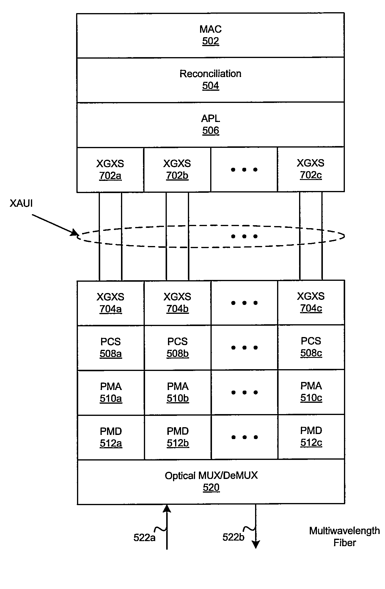
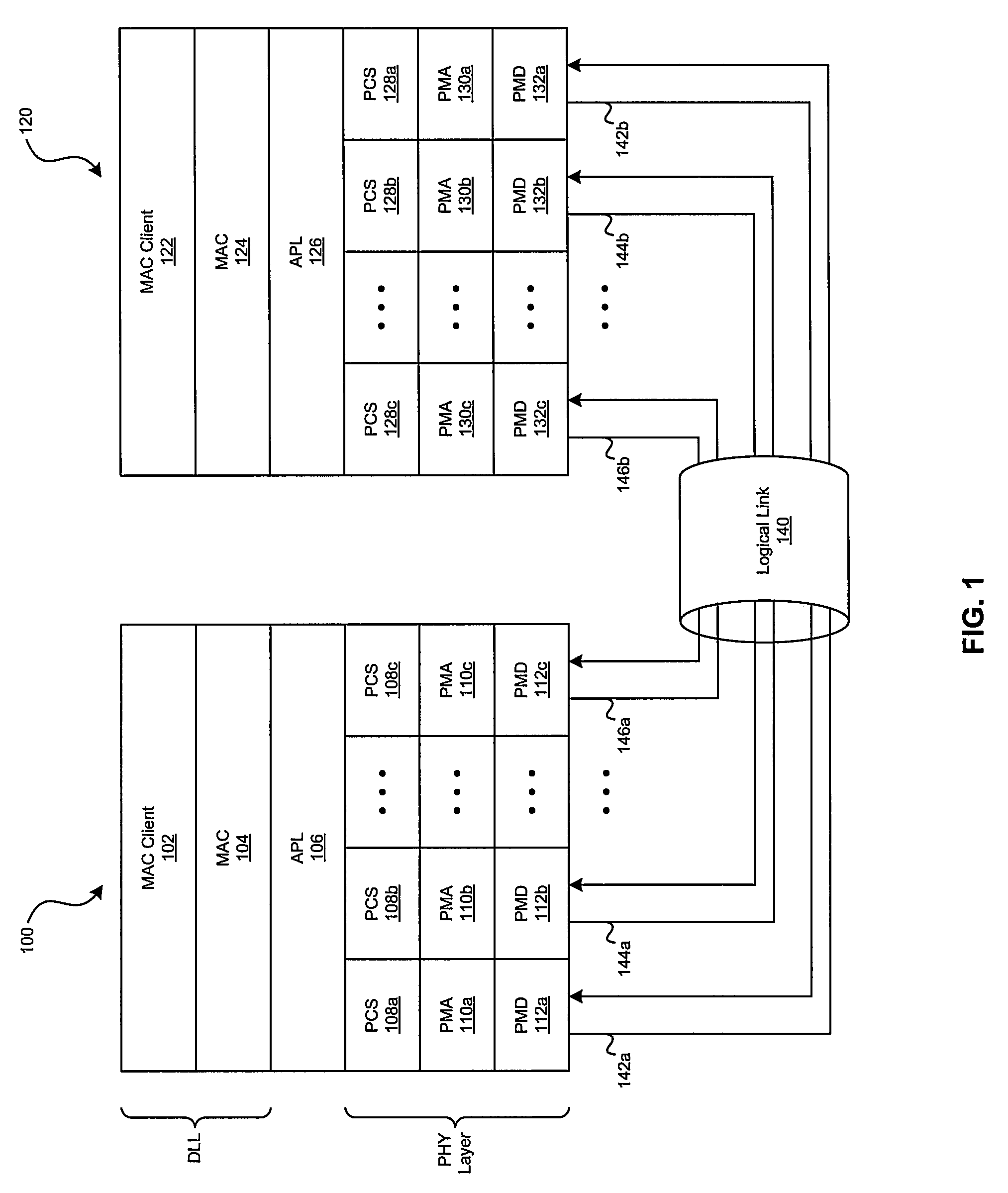
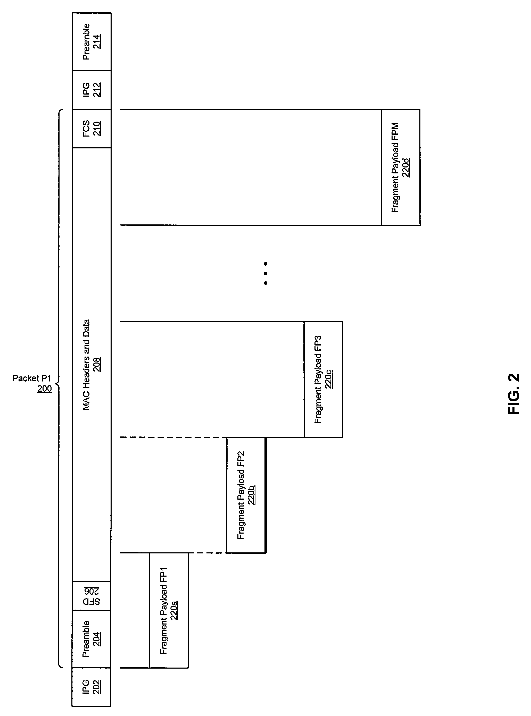
[0043]Certain embodiments of the invention may be found in a method and system for physical layer aggregation. Various embodiments of the invention may comprise an aggregation at the physical layer (APL) protocol entity, which may be located within the data link layer (DLL) or in the physical (PHY) layer. An instance of the APL protocol entity may receive packets, each of which may contain a preamble field and a frame start delimiter (FSD) field. The APL protocol entity instance may segment the contents of each packet into a plurality of fragment payload fields. For each fragment payload field, a fragment header field may be generated. For each fragment header field, a cyclical redundancy check (CRC) field may be generated. The CRC field may enable detection and / or correction of binary errors in the corresponding fragment header field. A corresponding plurality of fragments may be generated by appending the corresponding fragment header and CRC fields to each fragment payload field....


PUM


Abstract

Aspects of a system for physical layer aggregation may include one or more switch ICs and / or physical (PHY) layer ICs that enable reception of data packets via a medium access control (MAC) layer protocol entity. Each of the received data packets may be fragmented into a plurality of fragment payloads. Each of the plurality of fragment payloads may be sent to a PHY layer protocol entity instance a physical layer protocol entity instance selected from a plurality of physical layer protocol entity instances.

Description

CROSS-REFERENCE TO RELATED APPLICATIONS / INCORPORATION BY REFERENCE[0001]This application makes reference to, claims priority to, and claims the benefit of U.S. Provisional Application Ser. No. 60 / 862,742, filed on Oct. 24, 2006, which is hereby incorporated herein by reference in its entirety.FIELD OF THE INVENTION[0002]Certain embodiments of the invention relate to communication networks. More specifically, certain embodiments of the invention relate to a method and system for physical layer aggregation.BACKGROUND OF THE INVENTION[0003]Computer networks comprise a plurality of interconnected networking devices, such as routers, switches and / or computers. The physical connection that allows one networking device to communicate with another networking device is referred to as a link. Links may utilize wired or wireless communication technologies. Data may be communicated between networking devices via the link in groups of binary bits referred to as packets. The rate at which network...

Claims


Application Information

Patent Timeline
Patent Type & Authority Patents(United States)
IPC IPC(8): H04L1/00H04J3/04H04J3/22H04J3/00H04L12/26H04J3/16
CPCH04L69/14Y02B60/33Y02D30/50
Inventor FRAZIER, HOWARDTHALER, PATRICIAGHIASI, ALIBAUMER, HOWARD
Owner AVAGO TECH INT SALES PTE LTD
Why Eureka
Try Eureka