In-line microwave warming apparatus

a heating apparatus and microwave technology, applied in the field of inline microwave heating apparatus, can solve the problems of limiting the use and application of the apparatus, overheating fluid could severely overheat, and affecting the patient, so as to reduce the complexity and parts count, and minimize the cost of the apparatus

Inactive Publication Date: 2011-08-02
CORAL SAND BEACH LLC
View PDF6 Cites 32 Cited by
  • Summary
  • Abstract
  • Description
  • Claims
  • Application Information

AI Technical Summary

Benefits of technology

[0010]Accordingly, it is an object of the present invention to provide in-line microwave warming apparatus having dramatically reduced complexity and parts count which, in turn, minimizes the cost of the apparatus.
[0014]Another object of the invention is to provide in-line microwave warming apparatus of this type which is relatively easy to make and to operate.
[0017]In this case, however, the cartridge comprises a single turn or loop of tubing whose opposite ends are terminated by connectors. The tubing turn is supported and shaped by a flat, dielectric support member so that the tubing turn has opposite legs which are straight, coplanar and spaced apart a selected distance as will be described later. The cartridge is arranged to be slid into the slot in the waveguide so that the tube legs extend perpendicular to the longitudinal axis of the waveguide at the heating cavity. When the cartridge is so seated in the heating cavity, the slot and cartridge are sufficiently thin or narrow as to prevent leakage of radiation to or from the heating cavity.

Problems solved by technology

In other words, the fluid could severely overheat before the outlet transducer recognizes the problem.
Resultantly, when flow resumes, the overheated fluid could injure the patient.
While the above-described patented in-line microwave warmers provide distinct advantages over the prior water immersion-type warmers, they have certain drawbacks which may limit their use and application.
Still further, the two external transducers, three separate external radiometers and the multiple cables connecting the various temperature transducers to the radiometers, increase the overall complexity and footprint of the prior apparatus.

Method used


Image

  • In-line microwave warming apparatus
  • In-line microwave warming apparatus
  • In-line microwave warming apparatus

Examples


Embodiment Construction

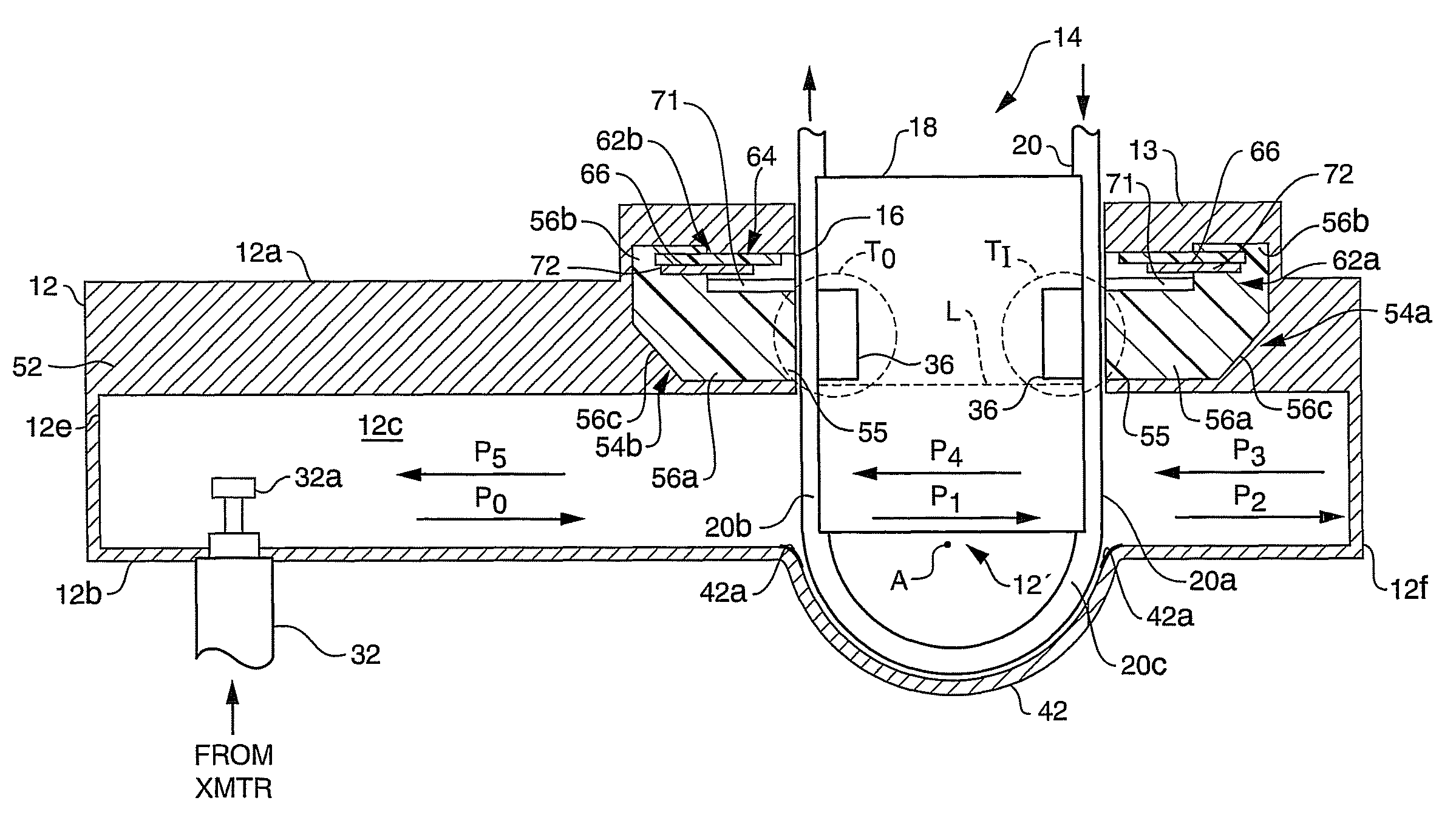
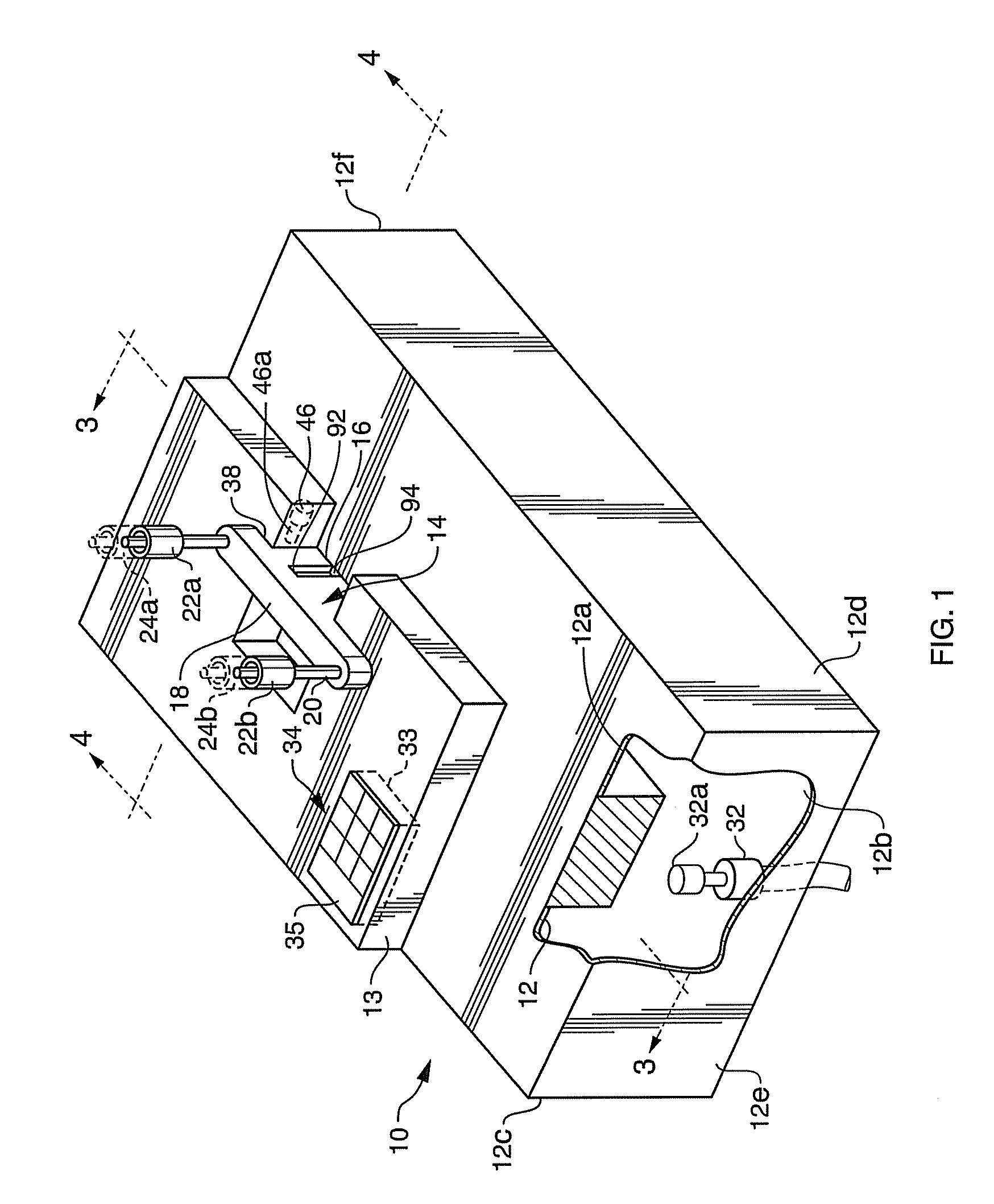
[0028]Referring to FIG. 1 of the drawings, my apparatus comprises a housing shown generally at 10 which defines a longitudinally extending waveguide 12 with a C-shaped promontory 13 atop the waveguide. The apparatus also includes a cartridge indicated generally at 14 which may be received in a slot 16 in housing 10 so that the cartridge protrudes through the arms of promontory 13 into the waveguide 12.

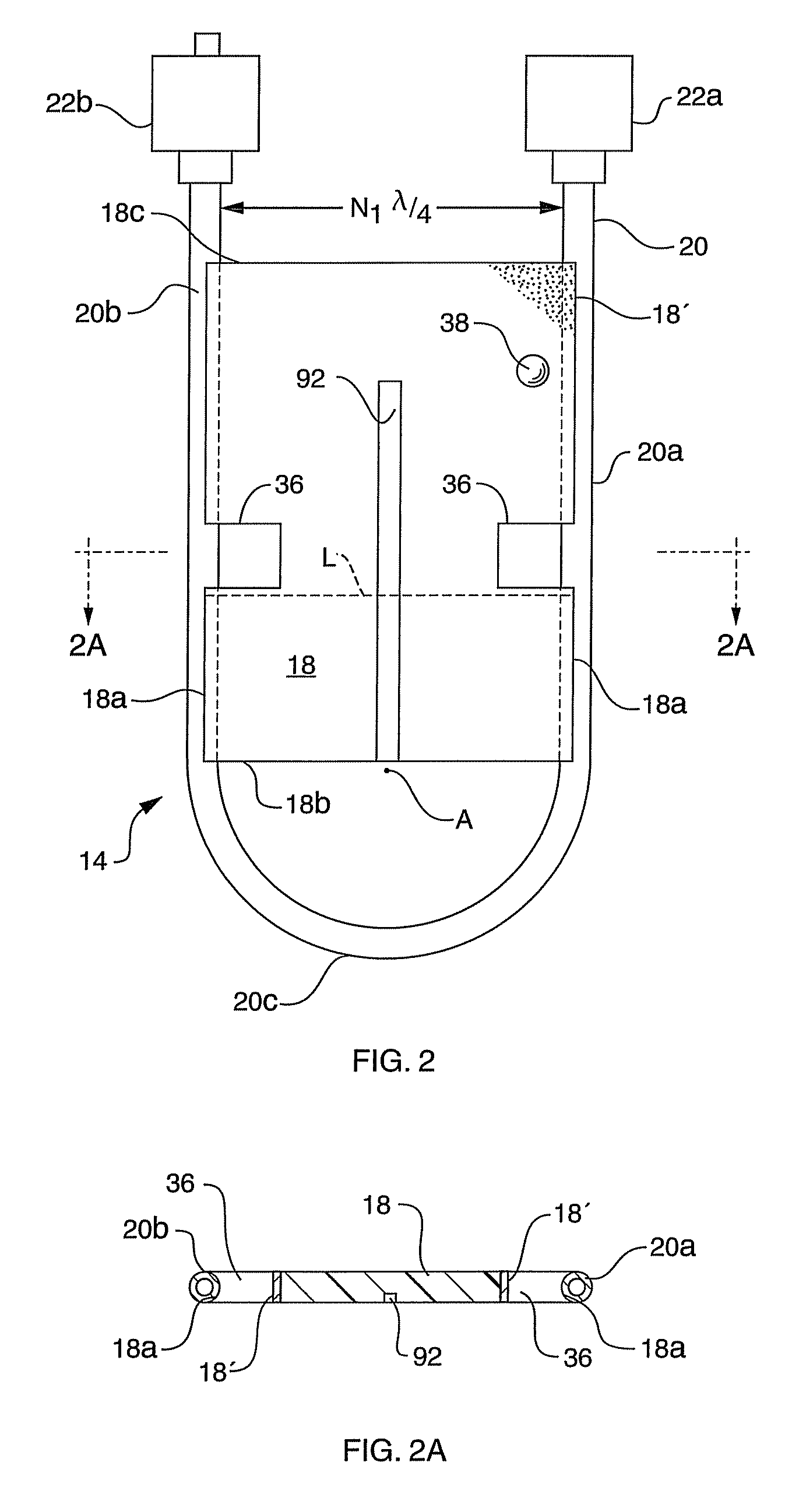
[0029]Cartridge 14 comprises a support member 18 which supports a length of tubing 20 whose opposite ends are terminated by conventional connectors 22a and 22b. Connector 22a, usually a female connector, may be connected to a mating connector 24a at the end of tubing leading to a source of fluid such as a blood bag or fluid administration set (not shown). Connector 22b, usually a male connector, may be connected to a mating connector 24b at the end of tubing leading to a fluid destination such as a catheter (not shown). As is evident from FIG. 1, the waveguide 12 has a pair of relative...


PUM


Abstract

Microwave warming apparatus includes a housing defining a heating waveguide with a heating cavity. An integral internal electrically conductive ridge projects from one of the longitudinal waveguide walls and extends along the waveguide. A slot having opposite ends extends from the outside through the ridge into the heating cavity, the slot being adapted to receive a cartridge containing a tube so that the tube extends through the slot into the heating cavity. Electromagnetic energy is coupled into the heating waveguide to heat the contents of the tube. A transducer constituted by a first receiving waveguide inside the ridge is adjacent to the slot so that when a cartridge is received in the slot, the transducer can sense the thermal radiation emanating from a segment of the tube and produce a corresponding waveguide-generated signal. A radiometer in the housing is responsive to the waveguide-generated signal and produces a temperature indicating signal.

Description

BACKGROUND OF THE INVENTION[0001]1. Field of the Invention[0002]This invention relates to in-line microwave warming apparatus for warming blood and other fluids.[0003]2. Background Information[0004]In many applications, particularly in the medical field, there may be a requirement that a circulating fluid be warmed. For example, in cardiac surgery during extra-corporeal circulation (ECC), the patient is first cooled in order to slow metabolism and thereafter the circulating blood is warmed to return it to body temperature. As another example, heated intravenous fluids are useful in hypothermic patients and in trauma patients requiring massive IV resuscitation.[0005]Microwave energy has, in the past, been used in connection with the heating of blood and intravenous fluids. For example, my U.S. Pat. Nos. 5,073,167 and 5,919,218, whose entire contents are incorporated herein by reference, disclose microwave apparatus comprising a waveguide heating cavity having a source of microwave en...

Claims


Application Information

Patent Timeline
Patent Type & Authority Patents(United States)
IPC IPC(8): H05B6/64H05B6/72A61F2/00
CPCA61M5/44H05B6/806A61M1/369A61M2205/3686A61M1/3623
Inventor CARR, KENNETH L.
Owner CORAL SAND BEACH LLC
Why Eureka
Try Eureka