
Motor controller and electric power steering apparatus

a technology of motor controller and electric steering, which is applied in the direction of motor/generator/converter stopper, dynamo-electric converter control, instruments, etc., can solve the problems of eps to change extremely its steering performance, conventional motor controller tends to make a worse steering feeling, and low output performance, so as to reduce the range and smooth the effect of the motor rotation

Inactive Publication Date: 2011-08-02
JTEKT CORP
View PDF9 Cites 4 Cited by
  • Summary
  • Abstract
  • Description
  • Claims
  • Application Information

AI Technical Summary

Benefits of technology

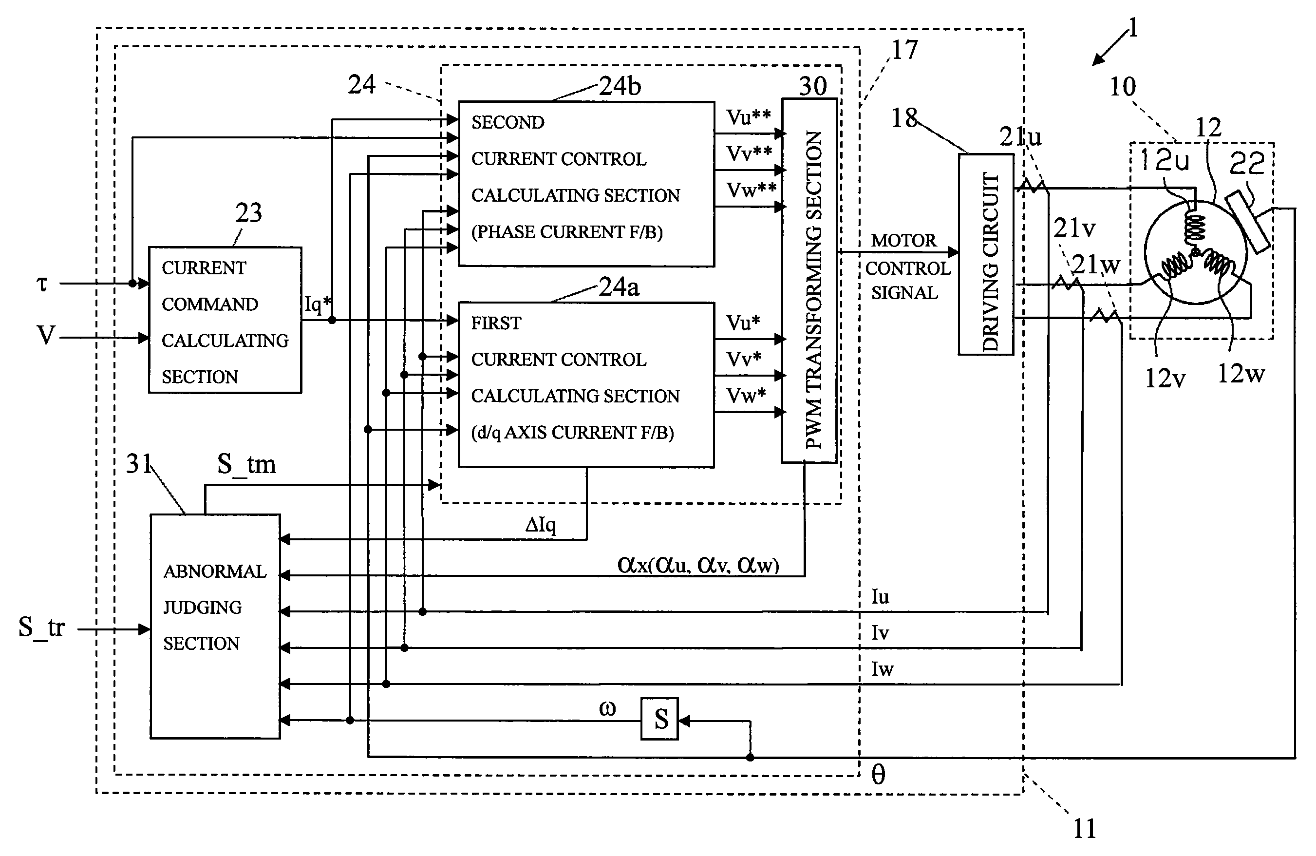
[0009]In view of the previously mentioned circumstances, it is an object of the present invention to provide a motor controller or an electric power steering apparatus provided with the motor controller to make a smooth rotation of a motor at two phases driving where a phase of a current-carrying failure is generated and to achieve a high output performance.
[0011]Based on the above construction, the motor current can be generated corresponding to a demand torque except for the predetermined rotational angle corresponding to the asymptote, or except for a current limit range adjacent to the predetermined rotational angle where there is an limitation on a phase current value carried the current in each phase of the motor. Thereby, there is no generation of a larger torque ripple to keep a high output performance with a continuation of the motor driving. By the correction of the phase offset between a current command value and an actual current value in the two phases driving, the present invention can reduce the range where there is an un-coincidence between a mark of the current command value and a mark of an actual current value generated adjacent to the predetermined rotational angle when the rotational angle of the motor passes the predetermined rotational angle corresponding to the asymptote, restraining a generation of the current rotating a reversal direction of the motor. Therefore, the phase offset between the current command value and the actual current value in the current control can be corrected to restrain the generation of the reversal assist so that the motor can be rotated smoothly without any sticking.
[0012]Second aspect of the present invention provides a motor controller or an electric power steering apparatus provided with the motor controller mainly having a motor control signal output member compensating the rotational angle to an advanced direction according to a rotational direction of the motor. There is any tendency that a phase angle of the actual current carried to the motor is delayed to a phase angle of the current command value because there are mechanical factor such as a back-lash in the motor, a delay of the calculation or a phase angle delay of the current control and so on. However, present invention constructed above can correct the phase delay of the actual current value to the current command value by advancing the rotation in advanced direction according to the rotational direction, thereby to achieve the smooth rotation of the motor.
[0013]Third aspect of the present invention provides a motor controller or an electric power steering apparatus provided with the motor controller mainly having a motor control signal output member compensating a rotational angle in a way that the faster a rotational angle velocity of the motor is, the larger a compensating amount of the rotational angle in the advanced direction is. There is any tendency that a delay of the phase angle of the actual current value to the phase angle of the command current value is happened more remarkably in accordance with the faster rotational angle velocity of the motor. Therefore, the present invention constructed above can accurately correct the delay of the phase angle of the actual current value to the phase angle of the command current value.
[0014]Fourth aspect of the present invention provides a motor controller or an electric power steering apparatus provided with the motor controller mainly having a current feedback control as the current control at the phase generated the current-carrying failure. It is pointed out that the most affective factor of an element of a time delay is the phase delay in the current feedback control. Therefore, the present invention constructed above can achieve more remarkable effects by the current feedback control executing the output of the motor control signal at the generation of the current-carrying failure.
[0015]Fifth aspect of the present invention provides a motor controller or an electric power steering apparatus provided with the motor controller mainly having a motor control signal output member executing said current feedback control in a d / q coordinate system without said generation of said current-carrying failure, and a phase current feedback control at said generation of said current-carrying failure. There is any tendency that the phase delay in a phase current feedback control is larger than that in a current feedback control of a d / q coordinate system. Therefore, the present invention constructed above can achieve more remarkable effects by the phase current feedback control executing the output of the motor control signal at the two phases driving.

Problems solved by technology

The abnormal state is a current-carrying failure in any phase of U, V, W of the motor by a wire breaking of a power supplying line and a terminal failure of a driving circuit.
However, there is a problem for the conventional EPS to change extremely its steering performance by the stop of the motor control.
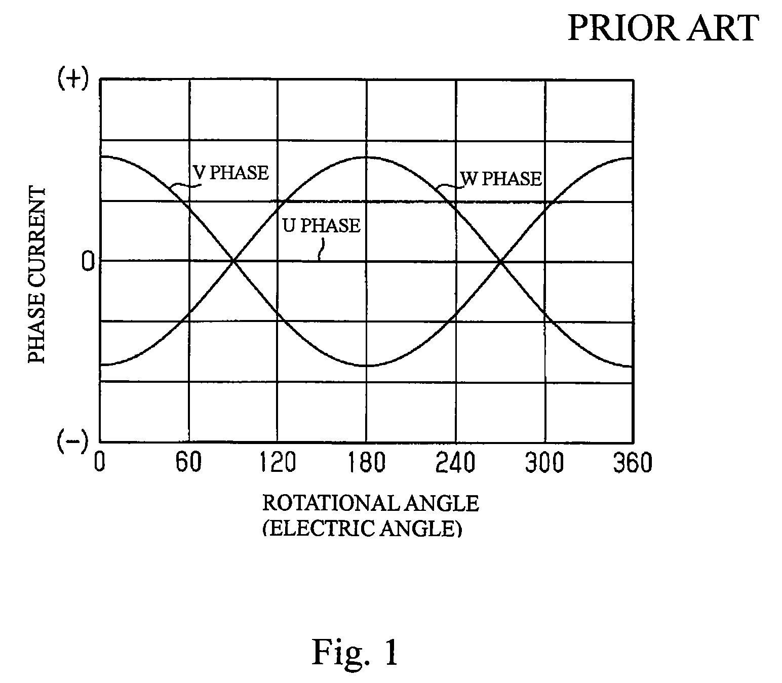
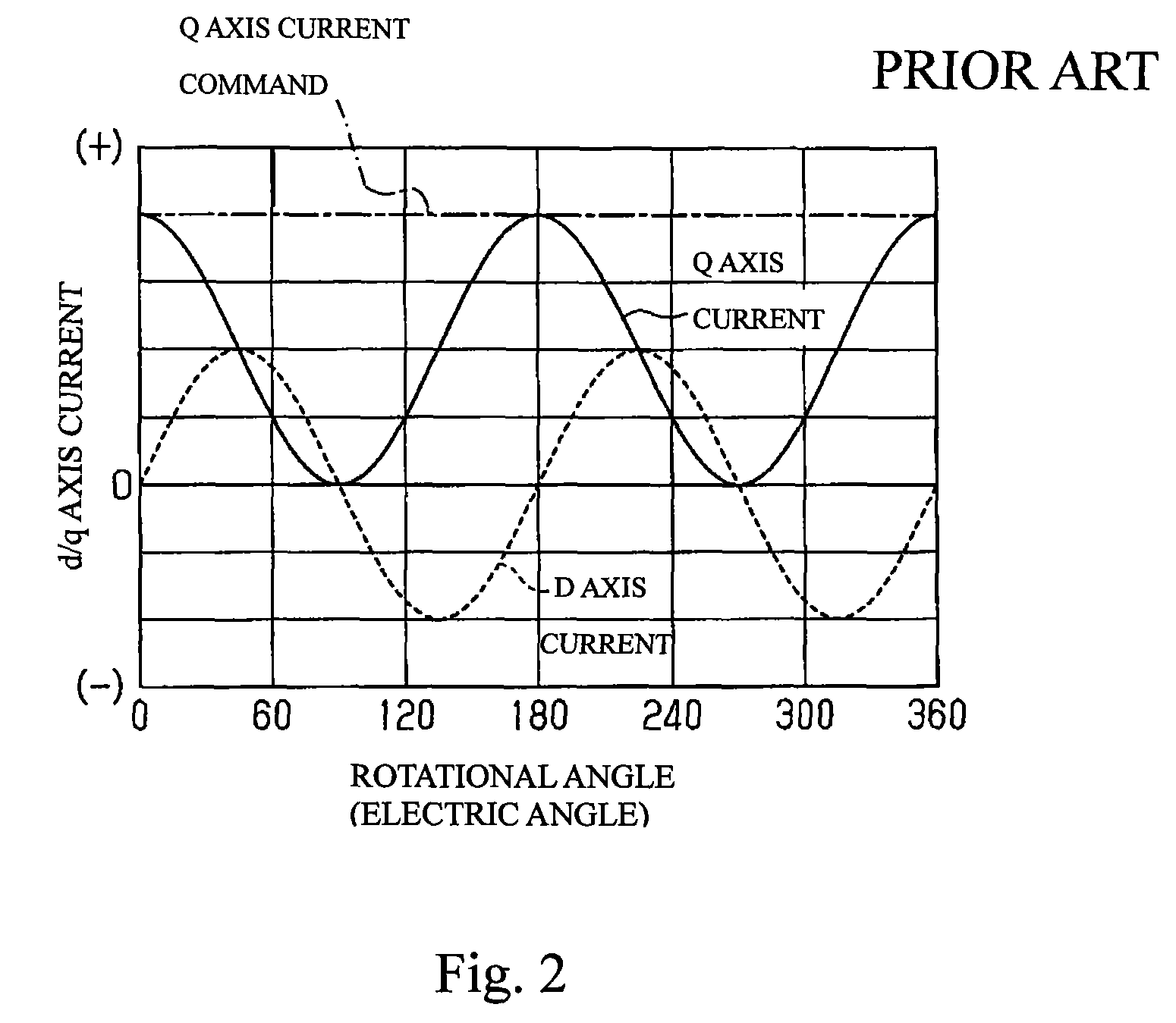
However, the conventional motor controller tends to make a worse steering feeling due to a generation of a torque ripple because of the construction to carry the current like a sine wave in a V phase and a W phase (the current-carrying failure in a U phase) of the current-carrying phases as shown in FIG. 1.

Method used


Image

  • Motor controller and electric power steering apparatus
  • Motor controller and electric power steering apparatus
  • Motor controller and electric power steering apparatus

Examples


case 1

[0065]Where there happens the current-carrying failure in the X phase (any one of U, V, W phases) by the wire breaking, the phase current value Ix in this happened phase is zero. There are other two cases listed hereinafter where the phase current value Ix becomes zero or almost zero other than the generation of the wire breaking:[0066]Case 1; where the rotational angle velocity of motor reaches to the maximum rotational number[0067]Case 2; where the current command value is almost zero itself.

[0068]In light of this two cases also, the one embodiment of the present invention operates at first to compare the phase current value Ix of the X phase to the predetermined value Ith to judge by this comparison whether the phase current value Ix is zero or not. Then it is to judge whether the detected state is in the Case 1, or 2 that the phase current value Ix is zero or almost zero in other condition than the wire breaking. Where there is neither in Case 1 nor in Case 2, it is judged as th...


PUM


Abstract

The micro computer 17 continue an output of a motor control signal to execute a current control to carry to each of two phases a phase current changing like a secant curve or a cosecant curve at making a predetermined rotational angle according to the phase generated the current-carrying failure as an asymptote at the generation of the current-carrying failure. The micro computer 17 provides a rotational angle compensating section 40 compensating an input rotational angle θ to correct a phase offset between a phase current command value Ix* as a current command value and an actual phase current value Ix as an actual current value in the current control.

Description

INCORPORATION BY REFERENCE[0001]The present application claims priority under 35 U.S.C. §119 to Japanese Patent Applications No. 2007-162985, filed on Jun. 20, 2007 and No. 2007-299476, filed on Nov. 19, 2007. The contents of the applications are incorporated herein by reference in their entirety.BACKGROUND OF THE INVENTION[0002]1. Field of the Invention[0003]The present invention relates to a motor controller and an electric power steering apparatus provided with the motor controller.[0004]2. Description of the Prior Art[0005]It is well known for a motor controller of an electric power steering apparatus (EPS) to stop a controller controlling its motor immediately after abnormal state is detected. The abnormal state is a current-carrying failure in any phase of U, V, W of the motor by a wire breaking of a power supplying line and a terminal failure of a driving circuit. Therefore, the motor controller is provided with an abnormal detecting member to detect a generation of the curre...

Claims


Application Information

Patent Timeline
Patent Type & Authority Patents(United States)
IPC IPC(8): H02P1/04
CPCB62D5/046B62D5/0484B62D5/0487H02P21/0035H02P29/022H02P21/22H02P29/032
Inventor TAMAIZUMI, TERUTAKA
Owner JTEKT CORP
Learn More