Fuel tank pressure indicator, including cap and container interface pressure indicator

a technology of fuel tank and interface, which is applied in the direction of instruments, machines/engines, anti-theft devices, etc., can solve the problems of fuel pump efficiency loss, fuel may not feed properly and efficiently into injectors or carburetors, and millions of gallons of fuel each year

Active Publication Date: 2011-08-02
RIGHTPSI
View PDF20 Cites 15 Cited by
  • Summary
  • Abstract
  • Description
  • Claims
  • Application Information

AI Technical Summary

Benefits of technology

It is an object of the invention to provide improved elements and arrangements thereof in an apparatus for the purposes described which is inexpensive, dependable and fully effective in accomplishing its intended purposes.

Problems solved by technology

Millions of gallons of fuel are lost each year due to ill-fitting fuel caps.
Losses may be caused by evaporation, expansion of the fuel as the fuel tank heats up when a vehicle is in operation, splashing, etc.
The vehicle's fuel pump may loose efficiency when the fuel cap is loose.
Fuel may not feed properly and efficiently into injectors or carburetors.
Loose fitting fuel caps may it more difficult for fuel feeding systems to get fuel to the combustion chambers with a proper air and fuel mixture.
As a result, motors become less efficient, and deliver less energy for the fuel used.
Motors generate excessive heat, due to inefficient or incomplete combustion.
Motors running on an inefficient fuel mixture have more friction because of increased heat and increased particulate matter resulting from incomplete combustion.
All of these factors result in decreased mileage, and in increased emissions and air pollutants.
(Unfortunately, only the English abstract and the drawing were available at the U.S. Patent & Trademark Office.)

Method used


Image

  • Fuel tank pressure indicator, including cap and container interface pressure indicator
  • Fuel tank pressure indicator, including cap and container interface pressure indicator
  • Fuel tank pressure indicator, including cap and container interface pressure indicator

Examples


Embodiment Construction

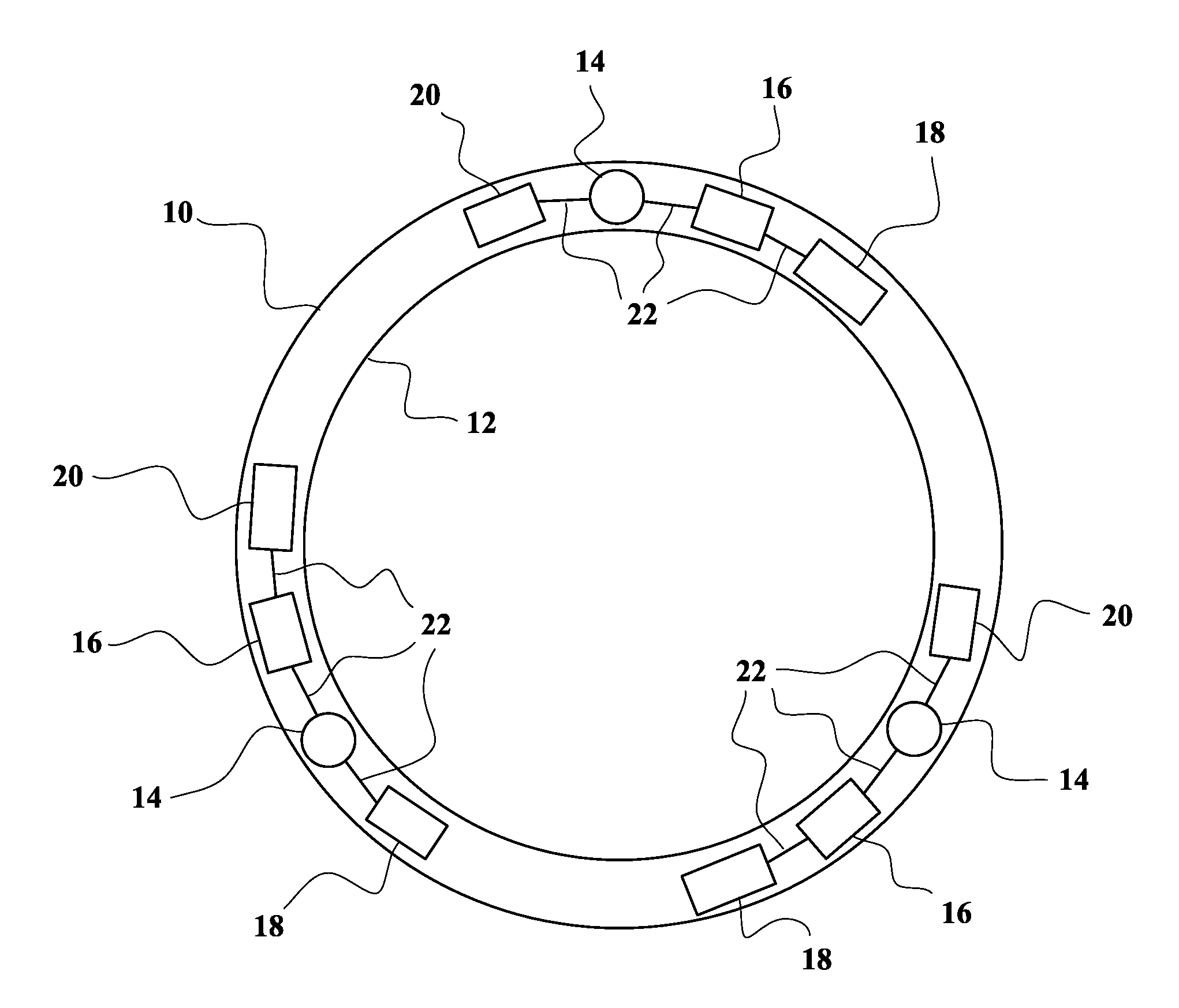
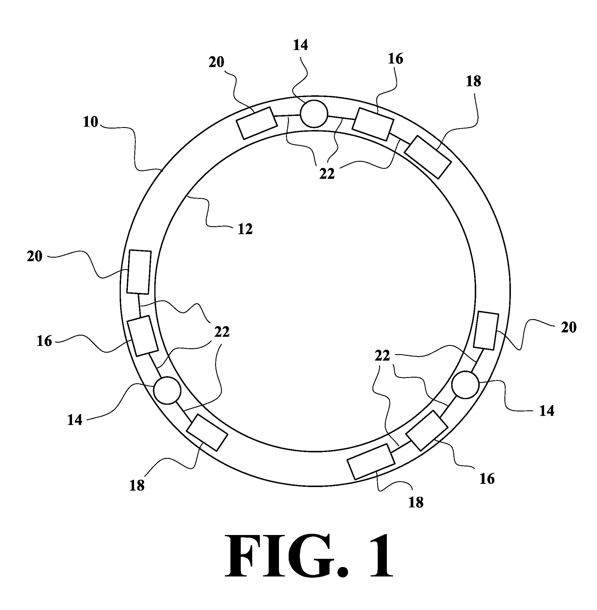
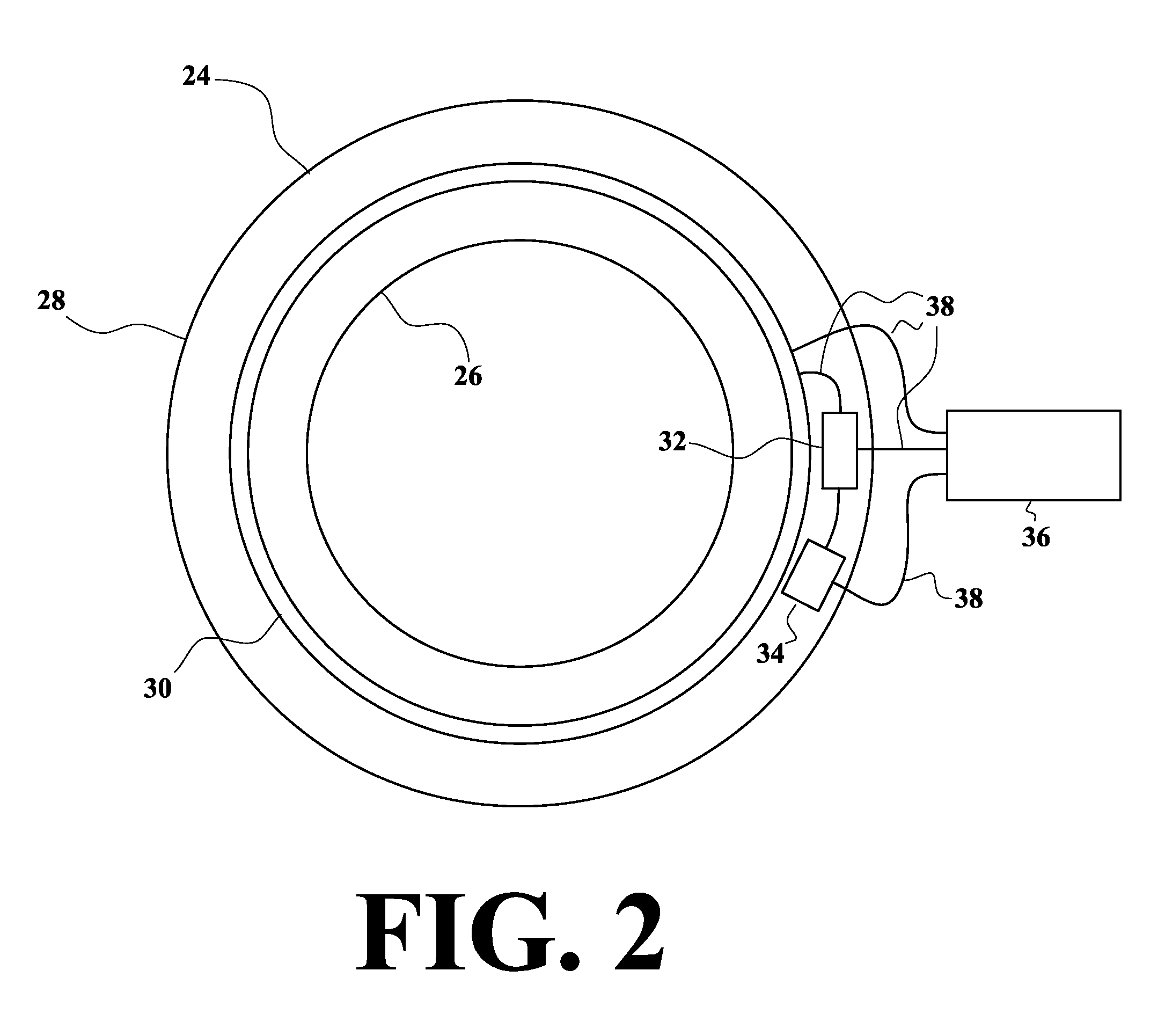
The present invention is a fuel tank pressure indicator, combining a sensor / transmitter in a fuel tank cap or the fuel tank itself, with a receiver / indicator, preferably in a key ring attachment. In the preferred embodiments, there are two versions of the sensor / transmitter that can be combined with any one of four versions of the receiver / indicator, to form a total of eight preferred embodiments. The first preferred embodiment combines the first sensor / transmitter with the first receiver / indicator. The second preferred embodiment combines the first sensor / transmitter with the second receiver / indicator. The third preferred embodiment combines the first sensor / transmitter with the third receiver / indicator. The fourth preferred embodiment combines the first sensor / transmitter with the fourth receiver / indicator. The fifth preferred embodiment combines the second sensor / transmitter with the first receiver / indicator. The sixth preferred embodiment combines the second sensor / transmitter w...


PUM

PropertyMeasurementUnit
pressureaaaaaaaaaa
Pressureaaaaaaaaaa
vapor pressureaaaaaaaaaa

Abstract

A pressure indicator for a motor vehicle (or other) fuel tank, that will indicate when pressure at the cap/container interface or vapor pressure in the tank drops below a predetermined level, which will normally mean that the fuel cap is not tightly secured to the tank's opening. The cap/container interface or vapor pressure will be detected by sensors in a rubber gasket (either in the cap or in the tank's opening that the cap fits over) or in a washer for the fuel cap. When the sensors detect a pressure below the predetermined level, BLUE TOOTH (or other appropriate) technology will be used to send a signal to a receiver (preferably in a key ring attachment) that will cause a red light to flash (or other appropriate visual, audio or tactile notice). The light may also flash when the cap is temporarily removed for refueling.

Description

BACKGROUND OF THE INVENTION1. Field of the InventionThe present invention relates to cap / container interface or vapor pressure indicators for fuel tanks, with sensors located in the cap for the fuel tank, in an opening of the fuel tank that the cap fits over, or in another part of the fuel tank.2. Description of the Prior ArtMillions of gallons of fuel are lost each year due to ill-fitting fuel caps. Losses may be caused by evaporation, expansion of the fuel as the fuel tank heats up when a vehicle is in operation, splashing, etc. The vehicle's fuel pump may loose efficiency when the fuel cap is loose. Fuel may not feed properly and efficiently into injectors or carburetors. Loose fitting fuel caps may it more difficult for fuel feeding systems to get fuel to the combustion chambers with a proper air and fuel mixture. As a result, motors become less efficient, and deliver less energy for the fuel used. Motors generate excessive heat, due to inefficient or incomplete combustion. Moto...

Claims


Application Information

Patent Timeline
Patent Type & Authority Patents(United States)
IPC IPC(8): G08B13/14C02F1/00H04Q5/22
CPCF02M37/0082
Inventor MILANOVICH, PHILIP JOHNMILANOVICH, JOHN KOSTIN
Owner RIGHTPSI
Why Eureka
Try Eureka