Inflatable floor for inflatable boat

a technology for inflatable boats and floor boards, which is applied in the field of inflatable floor boards for inflatable boats, can solve the problems of inability to provide stable support for people, cumbersome floor assembly, and inability to assemble and disassemble inflatable floor boards to and from boats, so as to improve structural stiffness, facilitate movement inside the boat, and improve the effect of structural rigidity

Inactive Publication Date: 2011-08-09
BAY INDAL
View PDF10 Cites 10 Cited by
  • Summary
  • Abstract
  • Description
  • Claims
  • Application Information

AI Technical Summary

Benefits of technology

[0016]Various aspects of the present invention provide an inflatable floor for an inflatable boat, which maintains stiffness without requiring a keel under the inflatable floor, provides a stable space in the inflatable boat so that a person can easily move inside the boat, so that cargo can be carried in a stable fashion and is light and easily packed.
[0017]Various aspects of the present invention also provide an inflatable floor for an inflatable boat which minimizes maintenance costs by facilitating partial replacement and / or repair even if one of the three inflatable floor layers is partially perforated or damaged, as well as greatly increasing its own buoyancy and strength so as to be easily applicable to a large inflatable boat such as a military or rescue boat having an overall length of 5 m or more.
[0018]In an aspect of the present invention, the inflatable floor is provided in the bottom of an inflatable boat to form a floor of the inflatable boat. The inflatable floor may include a first inflatable floor layer having a horizontally-planar cross section, a second inflatable floor layer provided under the first inflatable floor layer, a third inflatable floor layer underlying the second inflatable floor layer, and a plurality of ropes. The first inflatable floor layer includes upper and lower walls bonded with each other along edges to define an inflatable air chamber between the upper and lower walls and a plurality of links formed on the edges thereof at predetermined intervals. The second inflatable floor layer may include a plurality of inner links formed on the upper portion thereof, the inner links corresponding to the links of the first inflatable floor layer. On the second layer, the upper and lower walls are also bonded with each other along edges thereof to define an inflatable air chamber between the upper and lower walls, and a plurality of outer links formed on edges thereof at predetermined intervals. The second inflatable floor layer may have such a shape that a concave space is formed between the first and second inflatable floor layers. The third inflatable floor layer may include upper and lower walls bonded with each other along edges to define an inflatable air chamber between the upper and lower walls and a plurality of links formed along edges thereof at predetermined intervals. The links of the third inflatable floor layer may correspond to outer links of the second inflatable floor layer. The ropes may bind the first and second inflatable floor layers by passing through the links of the first inflatable floor layer and the inner links of the second inflatable floor layer, and bind the second and third inflatable floor layers by passing through the outer links of the second inflatable floor layer and the links of the third inflatable floor layer. With this configuration, the inflatable floor realizes a three-ply structure, which can greatly enhance structural strength and buoyancy, thereby maintaining stiffness. Additionally, the entire boat may be deflated and packed for transportation or storage with the floor in place and ready for immediate deployment the next time that the boat is put into service, without having to install the floor separately.

Problems solved by technology

However, it is labor intensive to assemble and disassemble the floor to and from the boat.
In addition, the floor is cumbersome since it is heavy and difficult to carry.
Rather, the inflatable floor 10 is flexible and does not provide stable support for a person who steps on the floor 10 in the inflatable boat 1.
As a result, it is difficult for the person to move inside the inflatable boat 1.
In this conventional structure, if the bottom 30 is punctured or torn, it no longer performs adequately as a hull due to air leakage.
Then, the inflatable boat 1 has great difficulty in navigating, its ability to stay afloat is reduced, and passengers' safety may be threatened.
However, even if air is filled into the inflatable floor 50, sufficient stiffness is not ensured.
Accordingly, this attempt is not applicable to the manufacturing of a large inflatable boat having an overall length of 5 m or more.

Method used


Image

  • Inflatable floor for inflatable boat
  • Inflatable floor for inflatable boat
  • Inflatable floor for inflatable boat

Examples


Embodiment Construction

[0035]Reference will now be made in detail to various embodiments of the present invention(s), examples of which are illustrated in the accompanying drawings and described below. While the invention(s) will be described in conjunction with exemplary embodiments, it will be understood that present description is not intended to limit the invention(s) to those exemplary embodiments. On the contrary, the invention(s) is / are intended to cover not only the exemplary embodiments, but also various alternatives, modifications, equivalents and other embodiments, which may be included within the spirit and scope of the invention as defined by the appended claims.

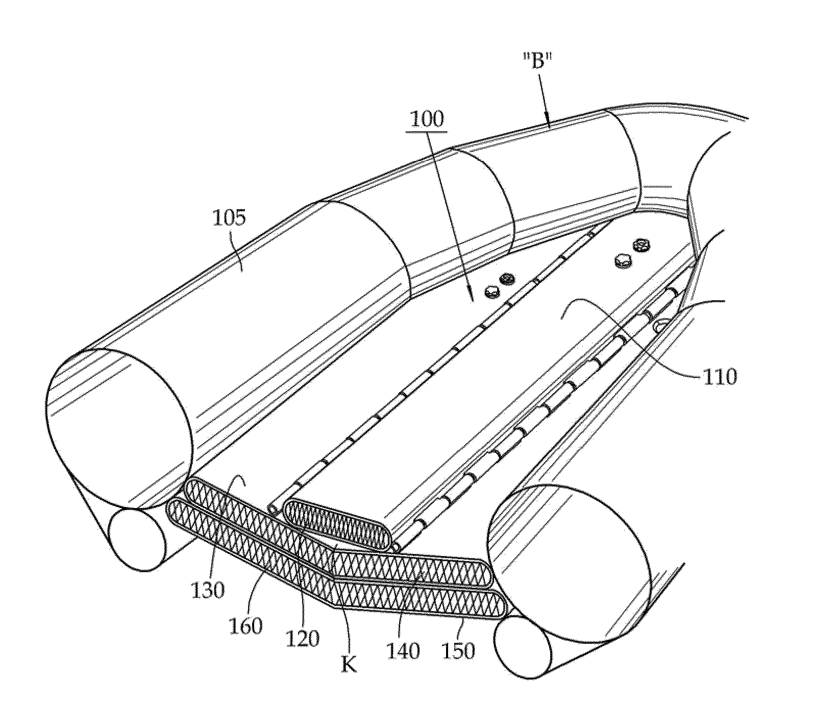
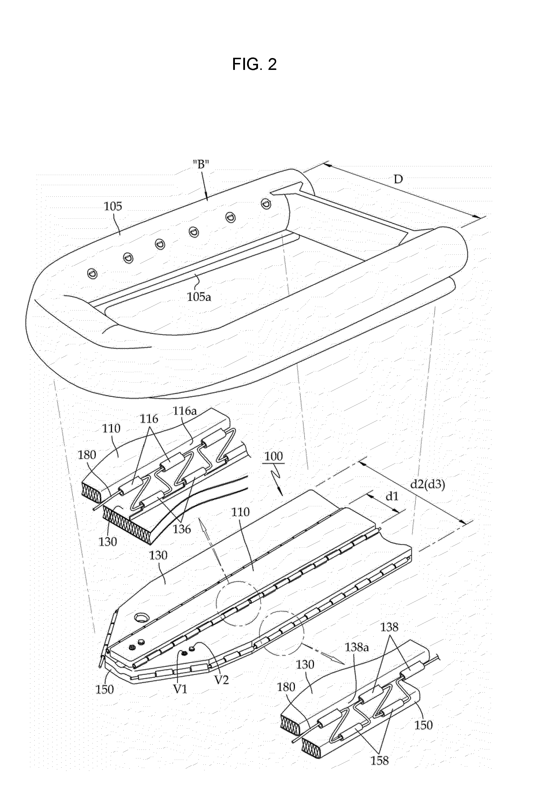
[0036]As shown in FIG. 2, an inflatable floor 100 for an inflatable boat in accordance with an exemplary embodiment of the invention is attached to the bottom of tubes 105 of an inflatable boat B, which maintain buoyancy using air or gas contained therein.

[0037]The inflatable floor 100 for an inflatable boat of this embodiment include...


PUM


Abstract

An inflatable floor for an inflatable boat acts as a keel using three inflatable floor layers. The uppermost first inflatable floor layer has a planar cross section. The second inflatable floor layer is located under the first inflatable floor layer. The third inflatable floor layer is located under the second inflatable floor layer. A plurality of threads are provided, in an X- or I-like configuration, inside air chambers of the three inflatable floor layers. The threads link the upper and lower walls of the air chamber of each respective inflatable floor layer to each other. The inflatable floor has increased buoyancy and stiffness, is easy to fold and transport and is easy and economical to repair or replace and thus is easily applicable to a large military or rescue inflatable boat.

Description

CROSS REFERENCE[0001]This application claims priority to Korean Patent Application Number 10-2009-74223 filed on Aug. 12, 2009, the entire contents of which application is incorporated herein for all purposes by this reference.BACKGROUND OF THE INVENTION[0002]1. Field of the Invention[0003]The present invention relates to an inflatable floor for an inflatable boat, in particular, to one which can act as a keel using three inflatable floor layers, which are bound to each other by ropes. Thereby, the inflatable floor can maintain stiffness so that a person can easily move inside the boat, enhance buoyancy to thereby increase capacity and minimize maintenance costs by facilitating partial replacement and / or repair even if one of the three inflatable floor layers is partially perforated or damaged. In addition, unlike a conventional inflatable boat, which must be packed by disassembling the bottom from the boat, the inflatable floor for an inflatable boat of the present invention can be...

Claims


Application Information

Patent Timeline
Patent Type & Authority Patents(United States)
IPC IPC(8): B63B7/00
CPCB63B3/38B63B7/08B63B7/085
Inventor CHON, DONG GYU
Owner BAY INDAL
Why Eureka
Try Eureka