Telescopic introducer with a compound curvature for inducing alignment and method of using the same

a technology of introducer and compound curvature, which is applied in the field of introducer with compound curvature for inducing alignment and the use of the same, can solve the problems of not being able to treat about 30% of stenoses located in the left circumflex artery with angioplasty, and the introduction of medical devices into the ostium of the coronary sinus is quite difficul

Active Publication Date: 2011-08-09
PRESSURE PROD MEDICAL SUPPLIES INC
View PDF5 Cites 137 Cited by
  • Summary
  • Abstract
  • Description
  • Claims
  • Application Information

AI Technical Summary

Benefits of technology

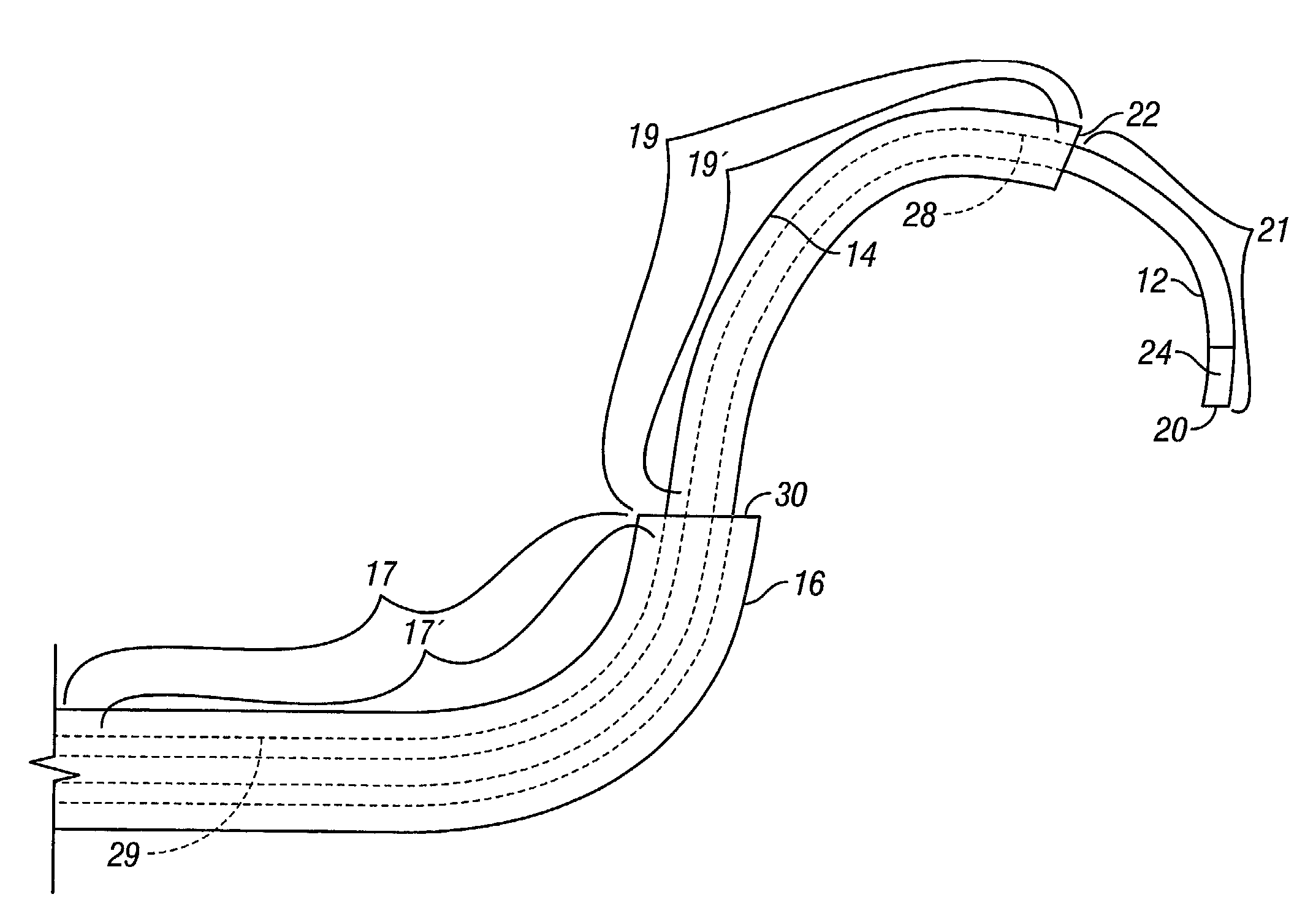
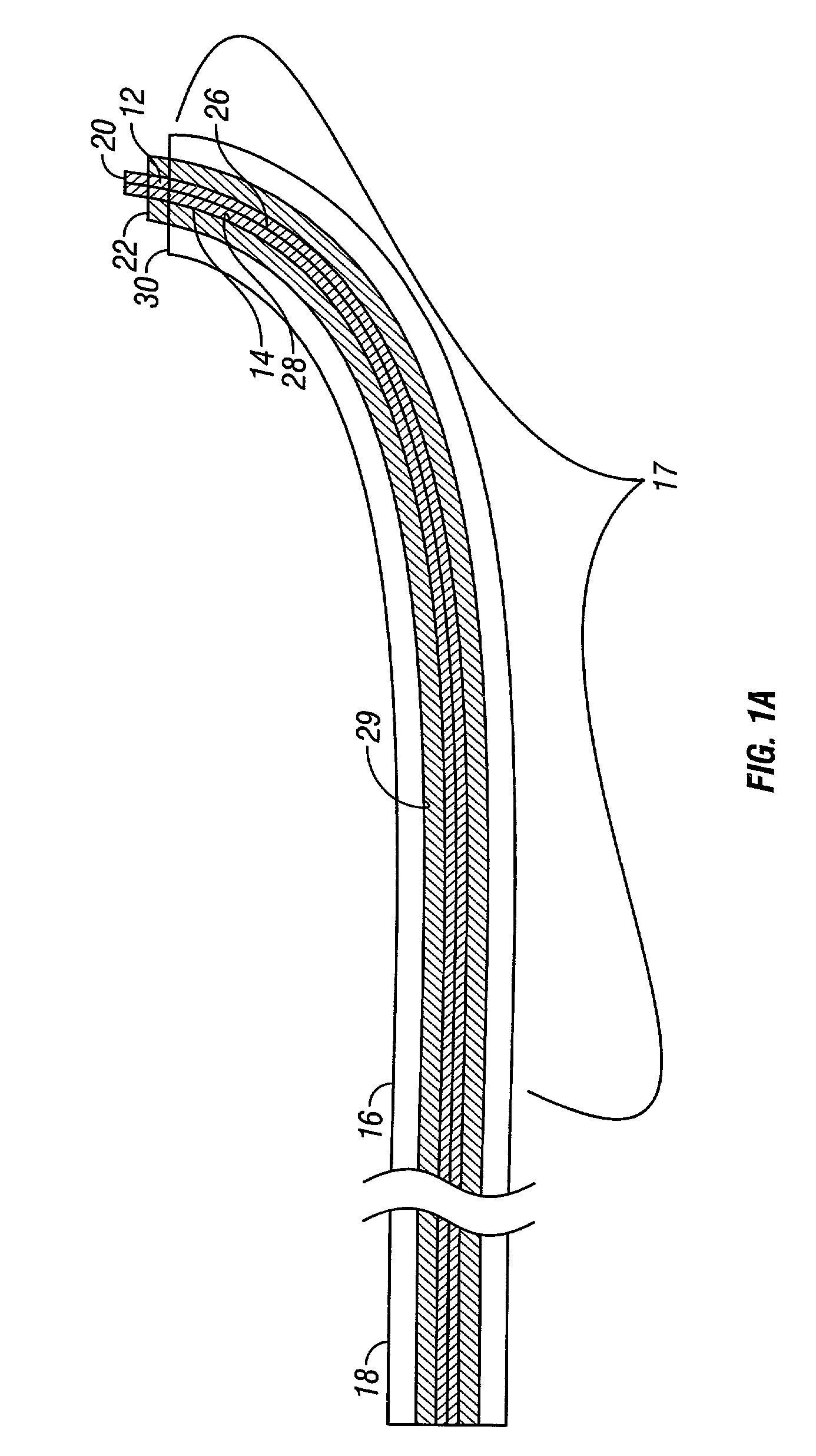
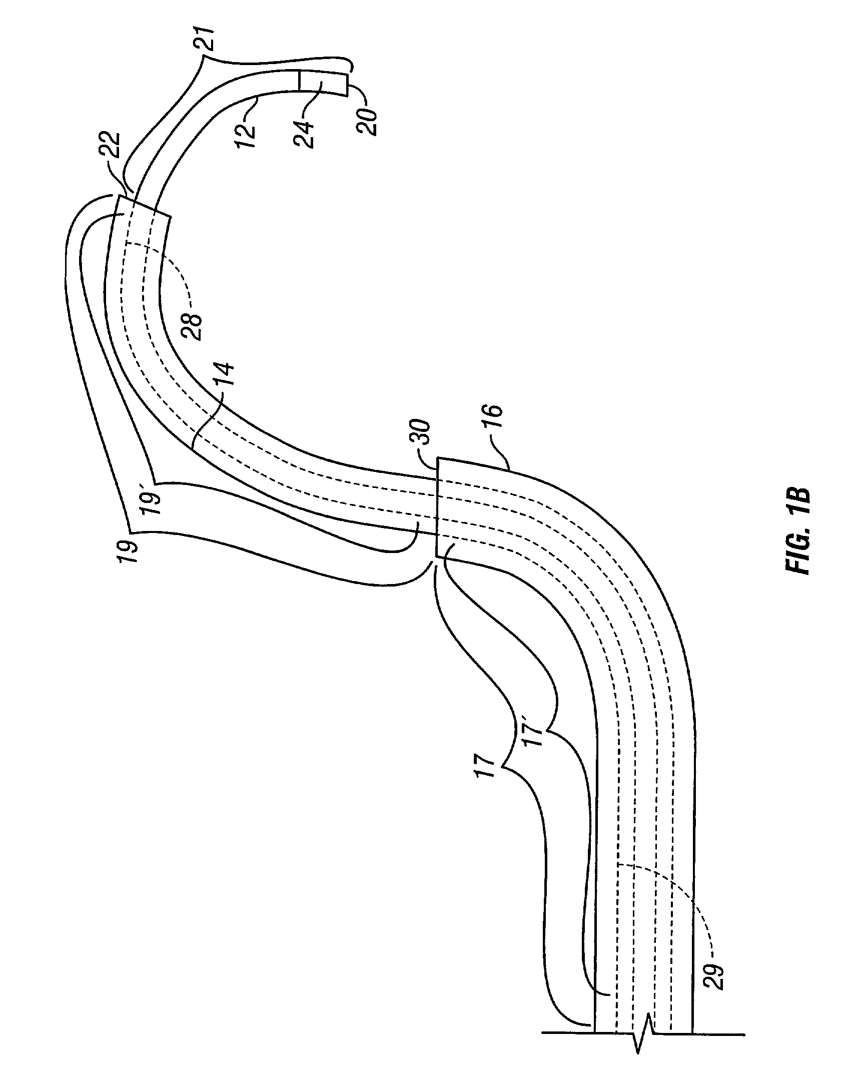
[0014]The invention is a telescopic introducer apparatus comprising a flexible, elongate, outer sheath, guide or introducer having a first shape or bias along a portion of its length. The outer sheath, guide or introducer is defined for the purpose of this specification and claims as an “outer elongate element”. The first shape may be anywhere along the length of the outer elongate element. The shape may be straight upon entry into the vascular system and be subsequently formed at the time of final placement. A flexible, elongate, telescopic inner sheath, guide, core or introducer has a second shape or bias on its distal portion and has the first shape or bias on a more proximal portion. The inner sheath, guide core or introducer is defined for the purpose of this specification and claims as an “inner elongate element”. The inner elongate element is telescopically disposed in the outer elongate element. The outer and inner elongate elements are relatively rotatable with respect to each other, such that when the inner elongate element is distally extended from the outer elongate element, there exists a mechanically or geometrically preferred angular orientation between the inner and outer elongate elements, which is congruent when there is at least partial alignment between the a portion of the outer elongate element and the more proximal portion of the inner elongate element, which two portions both have the first shape or bias. These respective portions are defined as “first-shape portions”.

Problems solved by technology

However, introduction of a medical device into the ostium of the coronary sinus is quite difficult as a result of the structure of the heart, the difficulty in locating the coronary sinus using conventional medical technology and the constantly changing shape of the heart while beating as well as the altered anatomy of the heart with cardiomyopathy.
The anatomy of the coronary sinus branch vein presents novel problems for cannulation and pacemaker insertion.
Although very few stenoses within the main coronary artery are so severe as to be impenetrable by a balloon catheter, about 30% of stenoses located in the left circumflex artery cannot be treated with angioplasty.
Such is the case because transmission of axial force to the distal end of the catheter from the proximal end is impeded by presence of a sharp bend where the catheter shaft traverses the intersection of the circumflex artery with the main artery.
The introducers by themselves are not capable of negotiating the branch vessels of the coronary arteries, but instead rely on the navigation of the wire to control the direction for subsequent guides to follow.
Any undue disturbance risks the dislodgment of that plaque with the possibility of a resulting heart attack or stroke.
However, a braided sheath, introducer and catheter means greater expense in fabrication of the sheath, introducer and catheter as well as a larger diameter of the sheath, introducer and catheter or a smaller inner diameter of any lumen in the sheath, introducer or catheter.
However, in this prior art case the inner guide 60 is rendered torqueable simply by having a sufficiently large enough diameter that it is rendered torsionally stiff given the material from which it is made.
However, shaped introducers whose shape has been optimized to access the coronary sinus have been found to have the wrong or an ill-adapted orientation or direction for any telescopic portion extending therethrough to access the venous system of the heart.
This then requires the physician to apply a substantial torque to the inner telescoping catheter to align the tip with the desired branch vessels, thereby making cannulation more difficult to accomplish and to maintain.

Method used


Image

  • Telescopic introducer with a compound curvature for inducing alignment and method of using the same
  • Telescopic introducer with a compound curvature for inducing alignment and method of using the same
  • Telescopic introducer with a compound curvature for inducing alignment and method of using the same

Examples


second embodiment

[0076]Similarly, in FIG. 5, what is shown is a plan elevational side view of one embodiment of splittable inner elongate element 14 of the invention. Again a proximal handle 42 is connected to a hub 44. A flexible sidearm tube 46 is communicated to hub 44 and is distally terminated with a hemostatic 48 through which contrast agent and other fluids may be injected into lumen 26 of inner elongate element 14. Inner elongate element 14 may lie in a single plane, such as the plane of FIG. 5. However, it is to be expressly understood that portions of inner elongate element 14 may be biased above or below the plane of FIG. 5 to provide an arbitrarily, three dimensionally shaped elongate element 14. Portion 36 is the defined as the proximal portion of inner elongate element 14 and is a generally unbiased, flexible section of inner elongate element 14 leading from the percutaneous introduction point into the left cephalic, auxiliary or subclavian veins and through the vasculature leading tow...

third embodiment

[0080]Still further, in FIG. 6, what is shown is a plan elevational side view of one embodiment of splittable inner elongate element 14 of the invention. Again a proximal handle 42 is connected to a hub 44. A flexible sidearm tube 46 is communicated to hub 44 and is distally terminated with a hemostatic valve 48 through which contrast agent and other fluids may be injected into lumen 26 of inner elongate element 14. Inner elongate element 14 may lie in a single plane, such as the plane of FIG. 6. However, it is to be expressly understood that portions of inner elongate element 14 may be biased above or below the plane of FIG. 6 to provide an arbitrarily, three dimensionally shaped elongate element 14. Portion 36 is the defined as the proximal portion of inner elongate element 14, proximal first shape, and is a generally prebiased but may be unbiased, flexible section of inner elongate element 14 leading from the percutaneous introduction point into the left auxiliary subclavian vein...


PUM


Abstract

An introducer system for implantation of pacemaker leads into the venous system of the human heart through the coronary sinus is comprised of a flexible, elongate, outer elongate element having a first shape or bias along a portion. The first shape on the outer element may be prebiased or may be initially straight and subsequently biased once deployed in the body chamber. A flexible, elongate, telescopic inner elongate element has a second shape or bias on its distal portion and has the first shape or bias on a more proximal portion. The inner elongate element is telescopically disposed in the outer sheath. The outer and inner elongate elements are rotatable with respect to each other, such that when the inner elongate element is distally extended from the outer sheath, there exists an angular orientation between the inner and outer sheaths which is congruent, when there is at least partial alignment between the distal portion of the outer elongate element and the more proximal portion of the inner sheath, both having the first shape or bias. This results in the rotation of the distal second shape or curve of the inner elongate element into a predetermined three dimensional location.

Description

BACKGROUND OF THE INVENTION[0001]1. Field of the Invention[0002]The invention relates to the field of catheters, guides, sheaths and introducers, which are utilized in a human heart. More particularly, this invention relates to a telescopic elongate cardiac instrument whose telescopic sections are made to align with each other.[0003]2. Description of the Prior Art[0004]The coronary sinus is the largest cardiac vein and serves as a conduit for access to various locations within the heart. Depending on the depth of insertion of the medical device into the coronary sinus, both the left and right atria and the left and right ventricles of the heart can be analyzed. However, introduction of a medical device into the ostium of the coronary sinus is quite difficult as a result of the structure of the heart, the difficulty in locating the coronary sinus using conventional medical technology and the constantly changing shape of the heart while beating as well as the altered anatomy of the he...

Claims


Application Information

Patent Timeline
Patent Type & Authority Patents(United States)
IPC IPC(8): A61B19/00A61M25/00A61F11/00A61MA61M25/01A61M25/08A61N1/00A61N1/05
CPCA61M25/0041A61N2001/0578A61N2001/0585
Inventor WORLEY, SETH J.KURTH, PAUL
Owner PRESSURE PROD MEDICAL SUPPLIES INC
Why Eureka
Try Eureka