Method and system for controlling the position of a beam of light

a beam of light and position control technology, applied in the field of free space optical communication systems, can solve the problems of inability to achieve dynamic range, inability to control bandwidth, and inability to achieve dc drift and 1/f noise, and achieve exceptional dynamic range and sensitivity, high angular precision, and wide bandwidth

Inactive Publication Date: 2011-08-09
LAWRENCE LIVERMORE NAT SECURITY LLC
View PDF12 Cites 7 Cited by
  • Summary
  • Abstract
  • Description
  • Claims
  • Application Information

AI Technical Summary

Benefits of technology

[0010]It is an object of the present invention to provide improvements in the dynamic range of free-space optical communication systems.
[0013]An improved method and system for laser beam tracking and pointing is described. It is based on a conventional position sensing detector (PSD) or quadrant cell but with the use of amplitude-modulated light. A unique combination of logarithmic automatic gain control, filtering, and synchronous detection offers high angular precision with exceptional dynamic range and sensitivity, while maintaining wide bandwidth. Use of modulated light enables the tracking of multiple beams simultaneously through the use of different modulation frequencies. It also makes the system resistant to interfering light sources such as ambient light. Beam pointing is accomplished by feeding back errors in the measured beam position to a beam steering element, such as a steering mirror. Closed-loop tracking performance is superior to existing methods, especially under conditions of atmospheric scintillation.

Problems solved by technology

One shortfall in the prior art is a lack of dynamic range, resulting in unacceptable compromises in pointing precision and / or control bandwidth.
This provides no rejection of ambient light or other interfering sources and is subject to DC drift and 1 / f noise.
Many approaches have used analog divider chips (e.g., Ontrak Photonics, Inc.) that are subject to offset errors, resulting in large errors at low signal levels.

Method used


Image

  • Method and system for controlling the position of a beam of light
  • Method and system for controlling the position of a beam of light
  • Method and system for controlling the position of a beam of light

Examples


Embodiment Construction

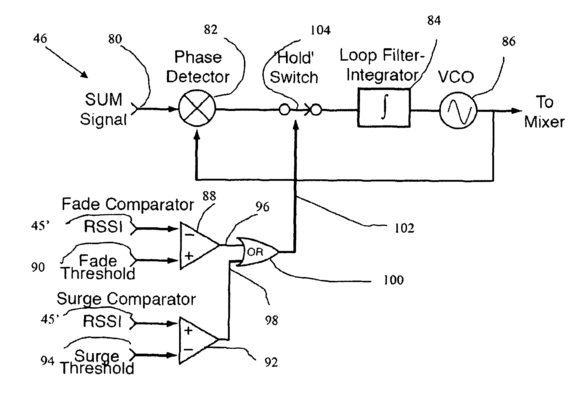
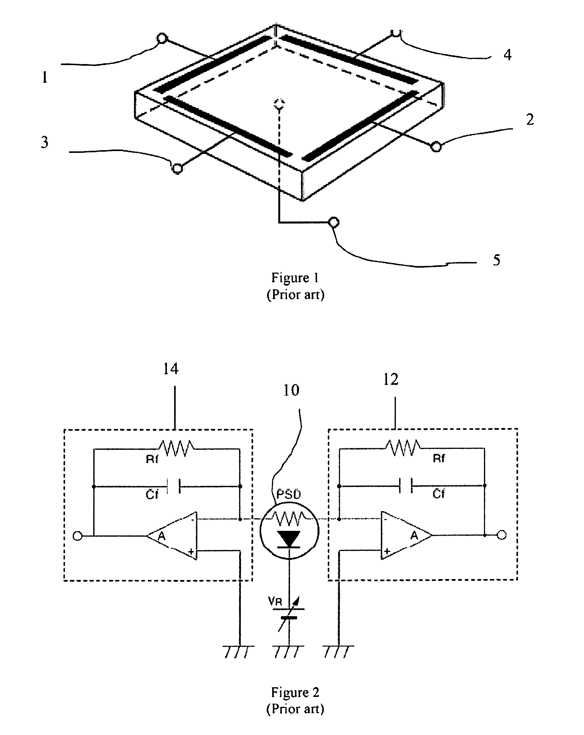
[0024]An improved method and system for laser beam tracking and pointing is described. It is based on a conventional lateral-effect position sensing detector (PSD) [Ref. 5, 6] or quadrant cell but with the use of amplitude-modulated light. Measured beam position on the face of the PSD is related to the beam's angle of incidence as defined by the properties of a series of lenses that collect the arriving beam and deliver it to the PSD. After detection and demodulation, the measured angle of arrival may be compared to a desired value (the setpoint). If an error exists, a correction command may then be sent to a steering mirror or other movable element to affect re-pointing of the receiving optical package. This closed-loop steering behavior is highly desirable for precise laser beam detection and delivery in many applications.

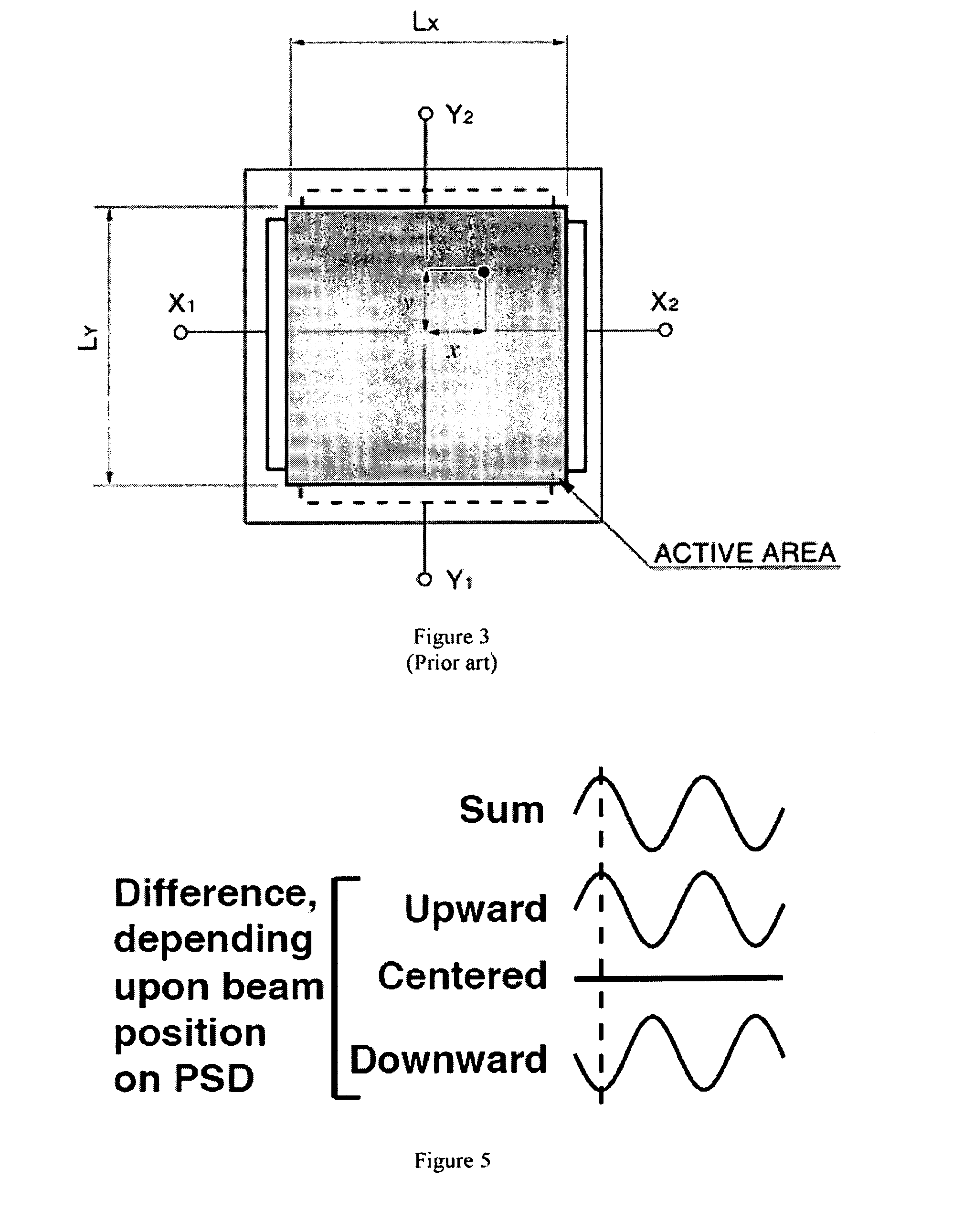
[0025]Position Detection

[0026]Detection of the PSD signals proceeds as follows [See Refs. 1-3 for tutorials]. A tetralateral (two-axis) PSD produces four current...


PUM


Abstract

An method and system for laser beam tracking and pointing is based on a conventional position sensing detector (PSD) or quadrant cell but with the use of amplitude-modulated light. A combination of logarithmic automatic gain control, filtering, and synchronous detection offers high angular precision with exceptional dynamic range and sensitivity, while maintaining wide bandwidth. Use of modulated light enables the tracking of multiple beams simultaneously through the use of different modulation frequencies. It also makes the system resistant to interfering light sources such as ambient light. Beam pointing is accomplished by feeding back errors in the measured beam position to a beam steering element, such as a steering mirror. Closed-loop tracking performance is superior to existing methods, especially under conditions of atmospheric scintillation.

Description

[0001]The United States Government has rights in this invention pursuant to Contract No. DE-AC52-07NA27344 between the United States Department of Energy and Lawrence Livermore National Security, LLC.BACKGROUND OF THE INVENTION[0002]1. Field of the Invention[0003]The present invention relates to free-space optical communication systems, and more specifically, it relates to improvements in the dynamic range of laser beam tracking in free-space optical communication systems.[0004]2. Description of Related Art[0005]Free-space optical communications systems are dependent upon the accuracy and stability of the pointing of a collimated laser beam. High stability must be maintained in spite of mounting platform vibrations, thermal drift, and especially atmospheric turbulence and scintillation which causes large and rapid fluctuations in beam position and intensity. A beam position sensing and feedback control system for stabilization is required and has been implemented in prior art by sev...

Claims


Application Information

Patent Timeline
Patent Type & Authority Patents(United States)
IPC IPC(8): G01C21/02
CPCG05B13/024H04B10/1121G02F2203/24
Inventor STEINKRAUS, JR., ROBERT F.JOHNSON, GARY W.RUGGIERO, ANTHONY J.
Owner LAWRENCE LIVERMORE NAT SECURITY LLC
Why Eureka
Try Eureka