Transcranial magnetic stimulation induction coil device and method of manufacture

a technology of induction coil and transcranial magnetic stimulation, which is applied in the direction of transformer/inductance casing, electrotherapy, therapy, etc., can solve the problems of generating a substantial amount of heat energy relatively quickly, reducing the time that a patient undergoing tms must endure such procedure, and resisting losses, etc., to reduce the rate of heat energy transfer, reduce the absorption rate of heat energy, and reduce the conductivity of phase transition material.

Active Publication Date: 2011-08-16
NEXSTIM
View PDF5 Cites 70 Cited by
  • Summary
  • Abstract
  • Description
  • Claims
  • Application Information

AI Technical Summary

Benefits of technology

[0013]In one embodiment of the TMS coil device, each of the coil windings in the TMS coil device includes inner and outer diameter surfaces and a fastener extending between and coupled to the inner and outer diameter surfaces, where the fastener preferably is only on one side of the coil winding. The fastener substantially fixes the size and shape of the coil winding.
[0016]In a further embodiment, the casting with the encased coil windings is coupled to and within the casing, such that a space is defined intermediate at least a portion of the casting and a portion of a bottom wall of the casing whose outer surface will be disposed adjacent or in contact with a subject's head during operation of the TMS coil device. The space includes at least one gas, preferably air, which reduces the rate of transfer of heat energy from the coil windings to the bottom wall of the casing.
[0017]In another embodiment, the portion of the casing on the side of the coil windings opposite to the bottom wall of the casing contains a phase transition material, which absorbs heat energy when transforming from solid to liquid and has a low conductivity, such as about 0.1-0.2 W / m*K. The low conductivity of the phase transition material reduces the absorption of heat energy from the coil windings into the casing. In one embodiment, the phase transition material is mixed with high conductivity material, such as ceramic, used to form the casing.

Problems solved by technology

In addition, during operation of a TMS coil device, resistive losses in the copper wire from which the coil windings are formed generate a substantial amount of heat energy relatively quickly, especially when the TMS coil device is operated to supply many sequential pulses to the brain.
The current limitations on the number of pulses that can be sequentially applied by a TMS coil device restricts the potential applications of the TMS coil device, and also lengthens the time that a patient undergoing TMS must endure such procedure, which is undesirable.
Such uses of fluid to increase the heat capacity of the TMS coil device, however, complicate the design and construction of the TMS coil device, which must be made waterproof, and also substantially increase the weight of the casing, which makes the TMS coil device more bulky and difficult to maneuver.
Therefore, it is disadvantageous for the coil windings to be positioned so far away from the casing outer surface portion that the maximum E-field that can be induced in the brain is undesirably diminished.

Method used


Image

  • Transcranial magnetic stimulation induction coil device and method of manufacture
  • Transcranial magnetic stimulation induction coil device and method of manufacture
  • Transcranial magnetic stimulation induction coil device and method of manufacture

Examples


Embodiment Construction

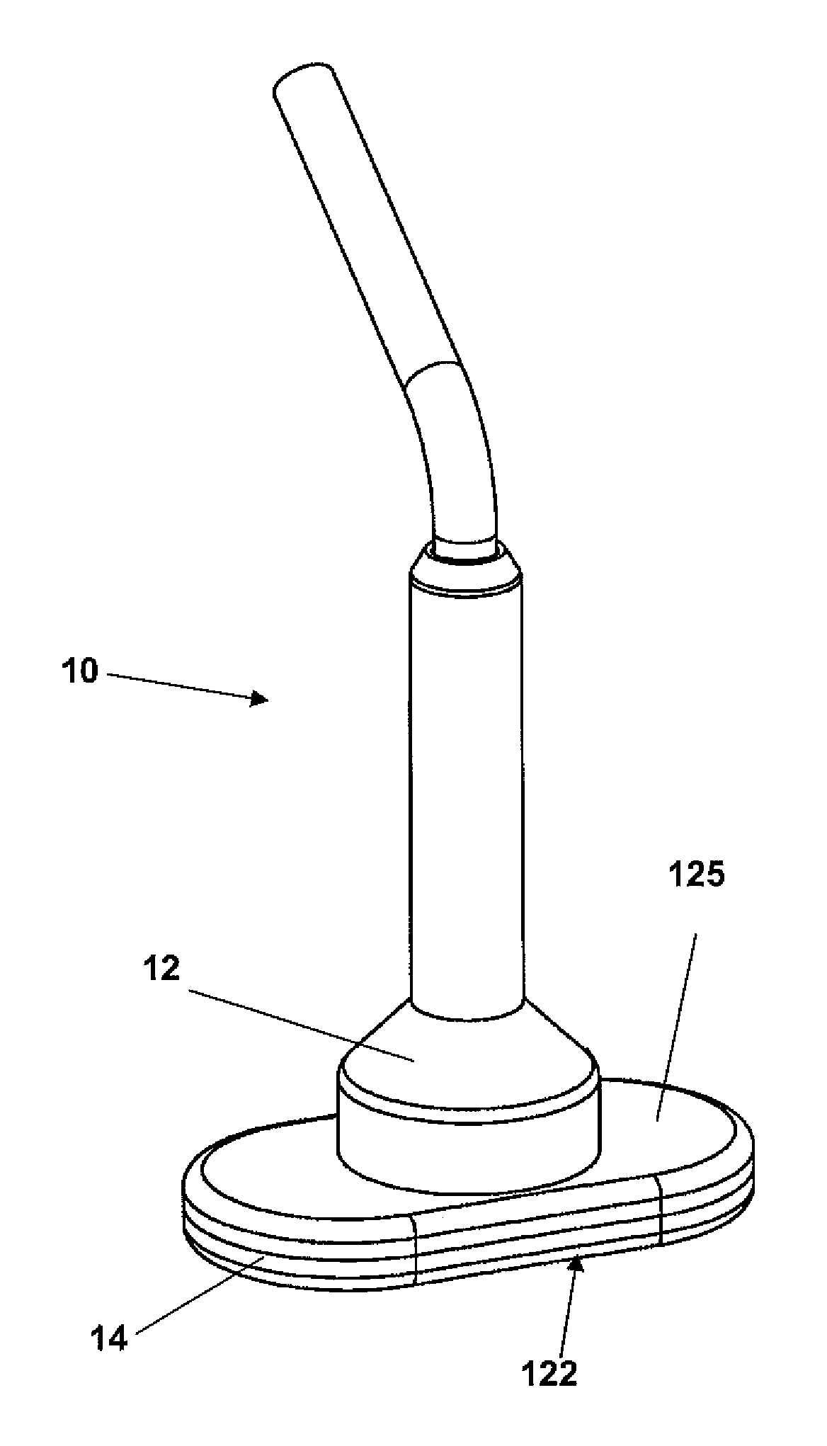
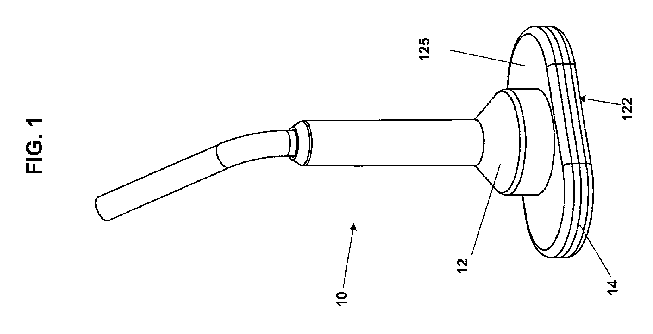
[0031]FIG. 1 is an exemplary embodiment of a TMS coil device 10, in accordance with the present invention, including a casing 12 containing induction coil windings 15 of predetermined size and shape, an exemplary embodiment of which is described in detail in the text accompanying the discussion of FIGS. 2-4, and substantially fixed, with a high level of precision, at a predetermined location within and orientation in relation to a bottom portion 14 of the casing 12. The casing 12 and an interior region of the bottom portion 14 of the casing 12 have a predetermined size and shape, as discussed in detail below in the text accompanying the discussion of FIGS. 4-5, such that the coil windings 15, when installed within the bottom portion 14 of the casing 15, is substantially precisely fixed at a predetermined location within and orientation in relation to the bottom portion 14 of the casing 12, and thus at a predetermined location and orientation in relation to a bottom outer surface 122...


PUM

PropertyMeasurementUnit
thicknessaaaaaaaaaa
temperatureaaaaaaaaaa
thicknessaaaaaaaaaa

Abstract

A transcranial magnetic stimulation induction coil device (“TMS coil device”) is manufactured to contain coil windings of a predetermined size and shape and fixedly positioned at a predetermined location within and orientation in relation to a casing of the TMS coil device. In one embodiment, the coil windings are encased in a casting at a predetermined location within and orientation in relation to the casting, and the casting is fixedly positioned at a predetermined location within and orientation in relation to the casing. The size and shape of the coil windings and the casing within, and the location and orientation of the coil windings in relation to each other and the casing of, the TMS coil device are known with a high level of precision, such that navigated brain stimulation can be performed with the TMS coil device with a high degree of accuracy. In another embodiment, the TMS coil device defines a space interposed between the coil windings and the casing and containing a gas which absorbs heat energy generated at the coil windings, thereby reducing the rate of transfer of heat energy from the coil windings to the casing during operation of the TMS coil device.

Description

CROSS REFERENCE TO RELATED APPLICATION[0001]This application claims the benefit of U.S. Provisional Application No. 60 / 823,991 filed Aug. 30, 2006, assigned to the assignee of this application and incorporated by reference herein.FIELD OF THE INVENTION[0002]The present invention relates generally to transcranial magnetic stimulation and, more particularly, to a transcranial magnetic stimulation induction coil device that can be navigated with a high level of precision.BACKGROUND OF THE INVENTION[0003]Transcranial magnetic stimulation (“TMS”) uses an induction coil to induce an electric field (“E-field”) within the brain. The locations of the brain exposed to a strong enough E-field will become activated, or stimulated. In navigated brain stimulation (“NBS”), the E-field induced in the brain by a TMS induction coil device is graphically represented on a display. As part of NBS, a three-dimensional (“3D”) localization system is used to locate the TMS coil device accurately with respec...

Claims


Application Information

Patent Timeline
Patent Type & Authority Patents(United States)
IPC IPC(8): A61N1/00
CPCA61N2/02A61N2/006Y10T29/49071
Inventor AHO, MATTI
Owner NEXSTIM
Why Eureka
Try Eureka