Method for reducing leakage currents caused by misalignment of a contact structure by increasing an error tolerance of the contact patterning process

a contact structure and error tolerance technology, applied in the field of semiconductor/solid-state device manufacturing, can solve the problems of forming unwanted leakage current paths, affecting the operation of circuit elements b, and certain amount of misalignment to be tolerated, so as to increase the error tolerance, reduce the probability of forming, and increase the effect of leakage curren

Active Publication Date: 2011-08-16
ADVANCED MICRO DEVICES INC
View PDF15 Cites 2 Cited by
  • Summary
  • Abstract
  • Description
  • Claims
  • Application Information

AI Technical Summary

Benefits of technology

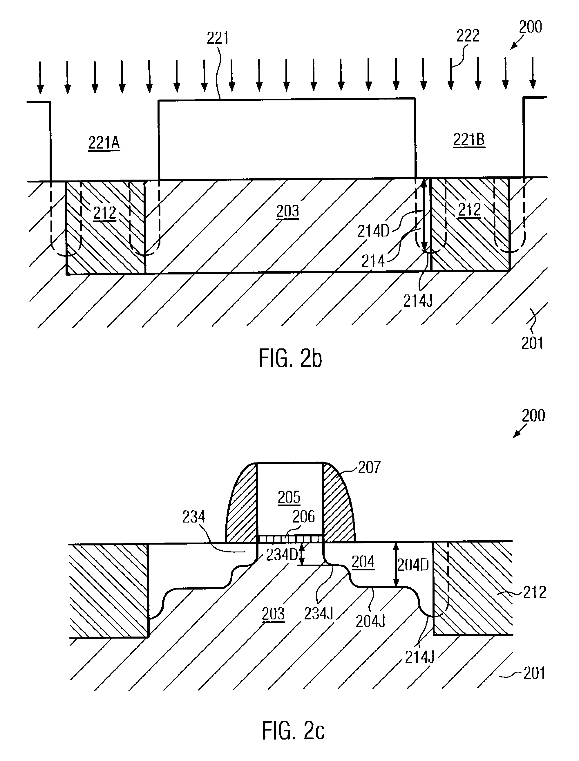
[0014]Generally, the present invention is directed to a technique that significantly increases the error tolerance during the formation of an interconnect structure, substantially without unduly affecting other device characteristics. In order to reduce the probability for the formation of contact irregularities, which, in conventional devices, may lead to increased leakage currents or electrical short circuits, the depth of a PN junction may be significantly increased, at least within an area in which a contact plug is to be formed, and / or by reducing the height of an active semiconductor region relative to the adjacent isolation trench, thereby significantly enhancing the performance of a corresponding alignment process during lithographical definition of respective contact openings. Consequently, additional floor space in the die for providing increased process tolerances, as is the case in some conventional techniques, may not be substantially consumed and hence the present invention is highly advantageous in combination with advanced semiconductor devices requiring extremely scaled circuit dimensions.

Problems solved by technology

Due to the large number of circuit elements and the required complex layout of modern integrated circuits, the electrical connections of the individual circuit elements may generally not be established within the same level on which the circuit elements are manufactured, but require one or more additional “wiring” layers, which are also referred to as metallization layers.
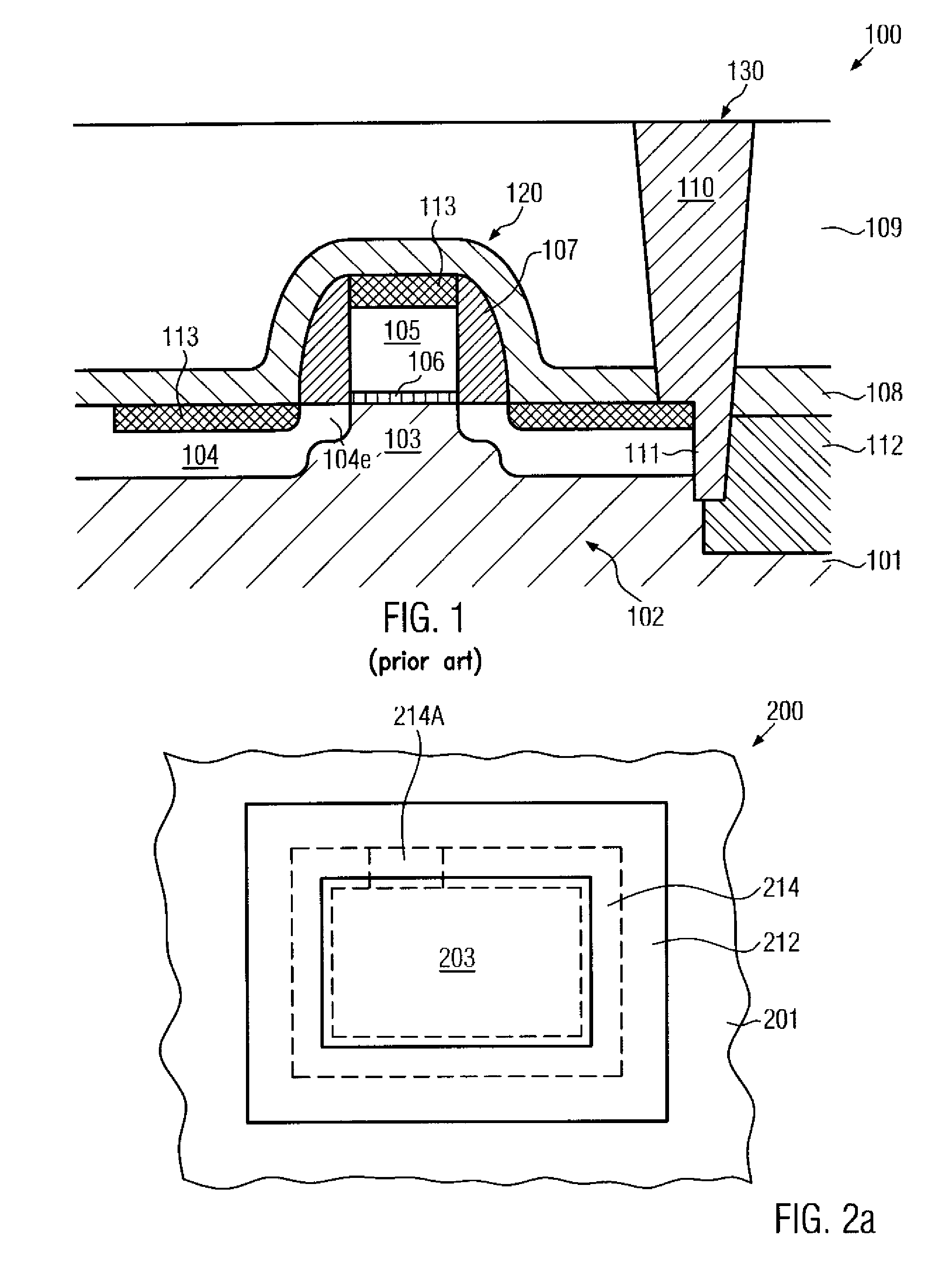
The formation of the contact openings is based on a photolithography step, during which the respective contact openings have to be aligned to respective contact regions of the circuit elements under question, such as source and drain regions of a transistor element, wherein, during the corresponding alignment procedure, slight misalignments may occur such that the corresponding contact opening may connect to undesired areas, such as an interface between an isolation trench and the active region, thereby resulting in a high risk for forming unwanted leakage current paths.
Typically, the alignment process is very critical and a certain amount of misalignment has to be tolerated due to unavoidable insufficiencies or inaccuracies during the lithography process.
In other cases, the corresponding metal protrusions 111 may provide increased leakage current paths, thereby also negatively affecting the operation of the circuit element 120.
Consequently, due to substantially non-avoidable insufficiencies of the corresponding photolithography process, reduced performance or even failure of the corresponding circuit element 120 may result after the formation of the respective interconnect structure 130.
However, increasing the area of the circuit element 120 that is available for receiving the contact plug 110 may be a less desirable option due to a significant increased amount of chip area which would be necessary in this case.

Method used


Image

  • Method for reducing leakage currents caused by misalignment of a contact structure by increasing an error tolerance of the contact patterning process
  • Method for reducing leakage currents caused by misalignment of a contact structure by increasing an error tolerance of the contact patterning process
  • Method for reducing leakage currents caused by misalignment of a contact structure by increasing an error tolerance of the contact patterning process

Examples


Embodiment Construction

[0024]Illustrative embodiments of the invention are described below. In the interest of clarity, not all features of an actual implementation are described in this specification. It will of course be appreciated that in the development of any such actual embodiment, numerous implementation-specific decisions must be made to achieve the developers' specific goals, such as compliance with system-related and business-related constraints, which will vary from one implementation to another. Moreover, it will be appreciated that such a development effort might be complex and time-consuming, but would nevertheless be a routine undertaking for those of ordinary skill in the art having the benefit of this disclosure.

[0025]The present invention will now be described with reference to the attached figures. Various structures, systems and devices are schematically depicted in the drawings for purposes of explanation only and so as to not obscure the present invention with details that are well ...


PUM


Abstract

By forming an additional doped region with increased junction depth at areas in which contact regions may connect to drain and source regions, any contact irregularities may be embedded into the additional doped region, thereby reducing the risk for leakage currents or short circuits between the drain and source region and the well region that may be conventionally caused by the contact irregularity. Moreover, additionally or alternatively, the surface topography of the semiconductor region and the adjacent isolation trench may be modified prior to the formation of metal silicide regions and contact plugs to enhance the lithography procedure for forming respective contact openings in an interlayer dielectric material. For this purpose, the isolation trench may be brought to an equal or higher level compared to the adjacent semiconductor region.

Description

BACKGROUND OF THE INVENTION[0001]1. Field of the Invention[0002]The present invention relates to the field of semiconductor manufacturing, and, more particularly, to the formation of an interconnect structure having contact plugs for connecting to contact regions of circuit elements, such as drain / source regions of a transistor.[0003]2. Description of the Related Art[0004]Semiconductor devices, such as advanced integrated circuits, typically contain a huge number of circuit elements, such as transistors, capacitors, resistors and the like, which are usually formed in a substantially planar configuration on an appropriate substrate having formed thereon a crystalline semiconductor layer. Due to the large number of circuit elements and the required complex layout of modern integrated circuits, the electrical connections of the individual circuit elements may generally not be established within the same level on which the circuit elements are manufactured, but require one or more addit...

Claims


Application Information

Patent Timeline
Patent Type & Authority Patents(United States)
IPC IPC(8): H01L21/336
CPCH01L21/76897H01L21/823475H01L21/823481
Inventor PETERS, CARSTENFROHBERG, KAIRICHTER, RALF
Owner ADVANCED MICRO DEVICES INC
Why Eureka
Try Eureka