X-ray analyzer and X-ray analysis method

a technology of x-ray analyzer and x-ray analysis method, which is applied in the direction of material analysis using wave/particle radiation, x/gamma/cosmic radiation measurement, instruments, etc., can solve the problems of low precision of distance measurement, difficult to obtain high sensitivity, and increased distance between x-ray source and sample, etc., to achieve high operability and high precision

Active Publication Date: 2011-08-16
HITACHI HIGH TECH SCI CORP
View PDF15 Cites 18 Cited by
  • Summary
  • Abstract
  • Description
  • Claims
  • Application Information

AI Technical Summary

Benefits of technology

[0010]In view of the above, it is an object of the invention to provide an X-ray analyzer and an X-ray analysis method which are excellent in operability when specifying a measurement position and which are capable of measuring distance with high precision.
[0013]Thus, in the X-ray analyzer and the X-ray analysis method, the surface of the sample is optically observed by the first observation system in order to determine the irradiation point, and the distance from the irradiation point is measured by focus adjustment using the second observation system which has a smaller depth of field than the first observation system and which can optically observe a narrow region. Accordingly, the high operability can be obtained by specifying the irradiation point with the first observation system which can observe a wide region and has a large depth of field, and the distance from the sample can be measured with high precision by the second observation system which can observe a narrow region and has a small depth of field.
[0016]That is, in the X-ray analyzer and the X-ray analysis method, the processing unit calculates the distance between the radiation source and the irradiation point on the basis of the distance from the irradiation point measured by the second observation system and corrects the result analyzed by the analyzer according to the distance. Accordingly, highly precise quantitative analysis and the like become possible by performing the correction on the quantitative calculation and the like.
[0017]Moreover, in the X-ray analyzer according to the aspect of the invention, it is preferable to further include: a sample stage on which the sample is placed; and a moving mechanism which moves the sample stage between an observation region based on the first observation system and an observation region based on the second observation system. The first and second observation systems may be disposed at different positions, and an optical component of the second observation system may be movably provided on an optical axis of a radial ray emitted from the radiation source. That is, in the X-ray analyzer, since the optical component of the second observation system is movably provided on the optical axis of the radial ray emitted from the radiation source, the second observation system is an optical system with a narrow field of view and a small optical component which can be disposed even in a small space may be used as an adopted optical component, such as a mirror. Accordingly, it becomes possible to bring the radiation source and the sample close to each other, compared with the case where the optical element of the first observation system is disposed on the optical axis. As a result, better sensitivity can be obtained.
[0019]That is, in the X-ray analyzer and the X-ray analysis method according to the aspects of the invention, the surface of the sample is optically observed by the first observation system in order to determine the irradiation point, and the distance from the irradiation point is measured by focus adjustment using the second observation system which has a smaller depth of field than the first observation system and which can optically observe a narrow region. Accordingly, high operability can be obtained by specifying the irradiation point with the first observation system which can observe a wide region and has a large depth of field, and the distance from the sample can be measured with high precision by the second observation system which can observe a narrow region and has a small depth of field.

Problems solved by technology

However, since a large space for the mirror is required in this case, the distance between the X-ray source and the sample is increased.
As a result, it is difficult to obtain high sensitivity.
For this reason, when performing distance measurement using an optical microscope which specifies the measurement position, there is a problem that the precision of the distance measurement is low because the depth of field was large.

Method used


Image

  • X-ray analyzer and X-ray analysis method
  • X-ray analyzer and X-ray analysis method

Examples


Embodiment Construction

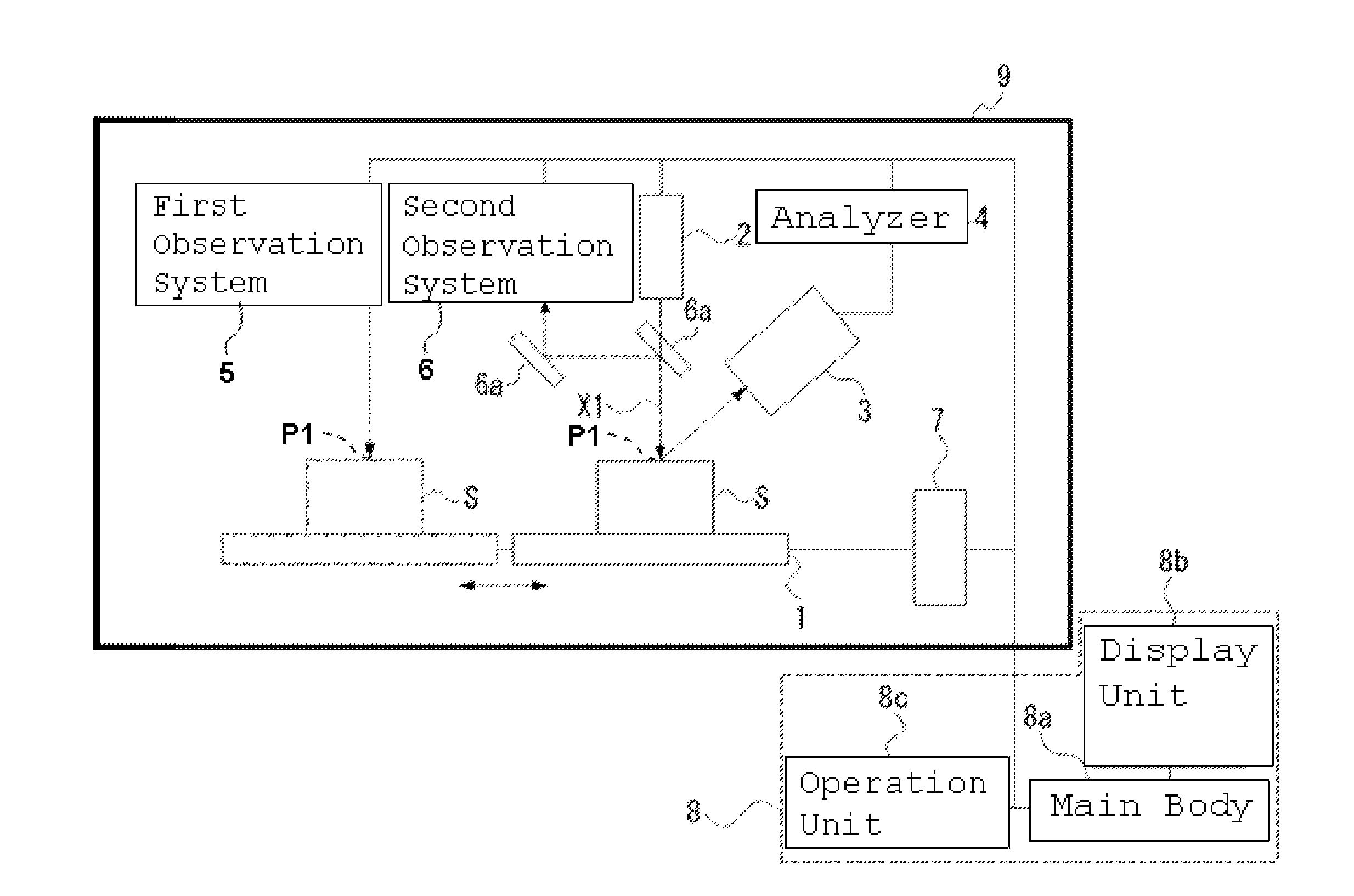
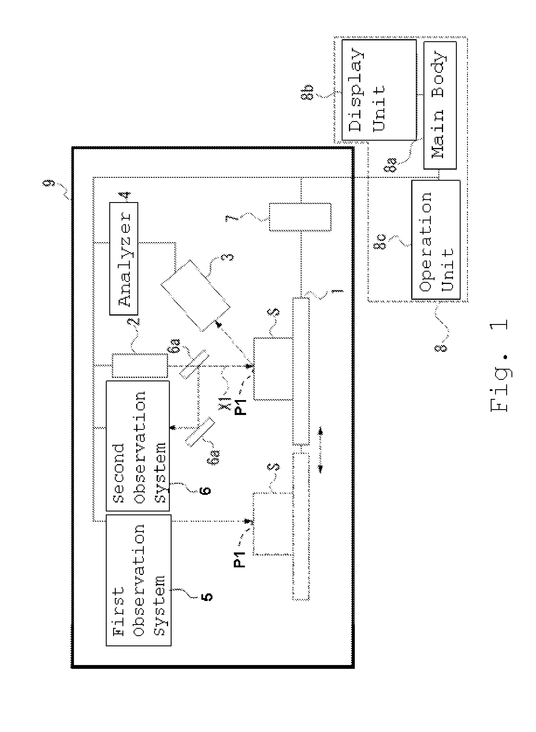
[0021]Hereinafter, an embodiment of the X-ray analyzer and X-ray analysis method according to the invention will be described with reference to FIGURE.

[0022]The X-ray analyzer of the present embodiment is an energy dispersive fluorescent X-ray analyzer, for example. As shown in FIGURE, the X-ray analyzer of the present embodiment includes: a sample stage 1 on which a sample S is placed and which is movable; an X-ray tube (radiation source) 2 which irradiates a primary X-ray (radial ray) X1 to an arbitrary irradiation point P1 on the sample S; an X-ray detector 3 which detects a characteristic X-ray and a scattered X-ray emitted from the sample S and outputs a signal including the energy information of the characteristic X-ray and scattered X-ray; an analyzer 4 which is connected to the X-ray detector 3 and analyzes the above signal; a first observation system 5 which can optically observe a surface of the sample S in order to determine the irradiation point P1; a second observation ...


PUM

PropertyMeasurementUnit
energyaaaaaaaaaa
distanceaaaaaaaaaa
depthaaaaaaaaaa

Abstract

An X-ray tube which irradiates a primary X-ray to an irradiation point on a sample, an X-ray detector which detects a characteristic X-ray and a scattered X-ray emitted from the sample and outputs a signal including energy information of the characteristic X-ray and scattered X-ray, an analyzer which analyzes the signal, a first observation system which optically observes a surface of the sample in order to determine the irradiation point, and a second observation system which has a smaller depth of field than the first observation system, optically observes a narrow region, and measures the distance from the determined irradiation point by focus adjustment are included.

Description

RELATED APPLICATIONS[0001]This application claims priority under 35 U.S.C. §119 to Japanese Patent Application No. JP2008-214716 filed on Aug. 22, 2008, the entire content of which is hereby incorporated by reference.BACKGROUND OF THE INVENTION[0002]1. Field of the Invention[0003]The present invention relates to an X-ray analyzer and an X-ray analysis method for performing fluorescent X-ray analysis and the like of a sample surface.[0004]2. Description of the Related Art[0005]In fluorescent X-ray analysis, an X-ray emitted from an X-ray source is irradiated onto a sample, a fluorescent X-ray which is a characteristic X-ray emitted from the sample is detected by an X-ray detector, and a spectrum is acquired from the energy and a qualitative analysis or quantitative analysis of the sample is performed. Fluorescent X-ray analysis is widely used in process management, quality management, and the like since a sample is quickly analyzed without being broken. In recent years, as measuremen...

Claims


Application Information

Patent Timeline
Patent Type & Authority Patents(United States)
IPC IPC(8): G01N23/223G01N23/203
CPCG01N23/223G01N2223/076
Inventor MATOBA, YOSHIKI
Owner HITACHI HIGH TECH SCI CORP
Why Eureka
Try Eureka