High frequency deflection measurement of IR absorption

a high frequency deflection and absorption technology, applied in the field of high-localized infrared (ir) spectra, can solve the problems of limiting the possible application, no real possibility of commercializing the set-up as published, and other deflection detectors may not generate as much information from the sample, etc., and achieve the effect of rapid pulse illumination

Active Publication Date: 2011-08-23
BRUKER NANO INC
View PDF5 Cites 32 Cited by
  • Summary
  • Abstract
  • Description
  • Claims
  • Application Information

AI Technical Summary

Benefits of technology

[0012]In certain other embodiments, the system includes a waveguide to direct energy from the source to the surface, thereby avoiding exposing the cantilever to radiation. In some embodiments, the cantilever may be the waveguide.
[0014]In various versions, the invention further includes causing the rep rate of the pulsed illumination to be rapid with respect to the imposed oscillation of the probe so that the characteristic behavior is continuously changed. Alternatively, it may be advantageous to cause the rep rate of the pulsed illumination to be slow with respect to the imposed movement of the probe so that the changes in characteristic behavior at the frequency of the pulses can be measured. In another alternative version, it may be beneficial to cause the rep rate of the pulsed illumination and the frequency of the imposed modulation to be set to create periodic interference at the beat frequency, thereby observing the effect on the characteristic force-distance behavior.

Problems solved by technology

Other deflection detectors may not generate as much information from the sample as the beam deflection detection.
Although the set-up as described produced positive results, there is no real possibility of commercializing the set-up as published.
For one thing, the requirement to place the sample on a prism to prevent exposing the lever to the IR pulse would limit the possible applications.
The actual signals generated can be small thus requiring averaging of the signal and limiting the bandwidth of the technique.
Moreover, an FEL is a very expensive and large device and only a few exist in the world.
Also, up to this point, the technique is not quantitative in terms of the amount of absorption that occurs in the local area.

Method used


Image

  • High frequency deflection measurement of IR absorption
  • High frequency deflection measurement of IR absorption
  • High frequency deflection measurement of IR absorption

Examples


Embodiment Construction

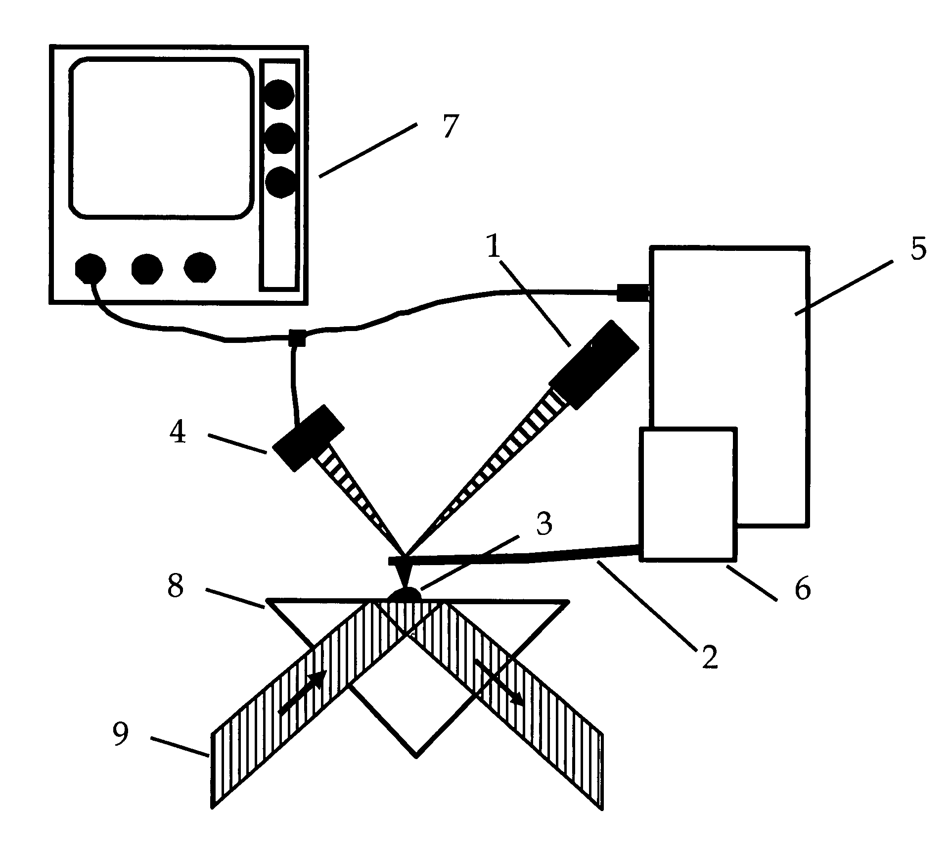
[0025]Referring to FIG. 3, cantilever 2, when shocked by the rapid thermal expansion of the sample rings with both ends basically fixed. This is not the normal deflection mode for an AFM cantilever. Typically an AFM cantilever tip end pivots about the fixed end. Therefore in normal operation the geometry that determines how much signal is generated for a given end deflection is a simple lever arm. For the current case, the deflection is more complex and the design of the cantilever to maximize the signal derived may be different then for a normal AFM cantilever. Moreover, depending on where the probe tip is on the sample, the induced oscillation may have a lateral component leading to a more complex signal. The existence of lateral vibration modes has been shown, and information can be derived from the lateral oscillations as well. The invention includes a cantilever of a specific design so that the contact resonance signal induced by the laser pulse is either amplified at a specifi...


PUM

PropertyMeasurementUnit
IR spectraaaaaaaaaaa
wavelengthaaaaaaaaaa
AFMaaaaaaaaaa

Abstract

An AFM based technique has been demonstrated for performing highly localized IR spectroscopy on a sample surface. Such a technique implemented in a commercially viable analytical instrument would be extremely useful. Various aspects of the experimental set-up have to be changed to create a commercial version. The invention addresses many of these issues thereby producing a version of the analytical technique that cab be made generally available to the scientific community.

Description

RELATED APPLICATIONS[0001]Not ApplicableFEDERALLY SPONSORED RESEARCH[0002]Not ApplicableSEQUENCE LISTING[0003]Not ApplicableBACKGROUND OF THE INVENTION[0004]This invention is related to highly localized Infrared (IR) spectra on a sample surface utilizing an Atomic Force Microscope (AFM) and a variable wavelength pulsed IR source.[0005]IR spectroscopy is a useful tool in many analytical fields such as polymer science and biology. It would be particularly useful to perform IR spectroscopy on a highly localized scale, on the order of biological organelles or smaller, at various points on a sample surface. Such a capability would provide information about the composition of surfaces, such as location of different materials or molecular structures. Recently, one of the inventors has developed a technique based on use of an AFM in a unique fashion to produce such localized spectra. This work was described in a publication entitled “Local Infrared Microspectroscopy with Sub-wavelength Spat...

Claims


Application Information

Patent Timeline
Patent Type & Authority Patents(United States)
IPC IPC(8): G01B5/28G01N21/84G01Q80/00G01Q30/00G01Q60/32G01Q60/38
CPCB82Y35/00G01N21/35G01Q60/32G01Q60/38G01Q30/02G01N21/3563
Inventor DAZZI, ALEXANDREPRAZERES, RUIKJOLLER, KEVINREADING, MICHAEL
Owner BRUKER NANO INC
Why Eureka
Try Eureka