
Breath and breath condensate analysis system and associated methods

a breath condensate and analysis system technology, applied in the field of breath condensate analysis systems and methods, can solve the problems of discomfort for patients, time-consuming and expensive breath test methods, and analytical methods that require a trained technician and laboratory, and achieves convenient and fast analysis, simple use, and high volume studies and/or clinical use.

Inactive Publication Date: 2011-08-23
EULIANO NEIL R
View PDF25 Cites 23 Cited by
  • Summary
  • Abstract
  • Description
  • Claims
  • Application Information

AI Technical Summary

Benefits of technology

"The present invention is a breath and breath condensate analysis instrument that includes a disposable element and a non-disposable element. The disposable element includes an inlet for receiving expired breath and a condensate trap for holding and condensing the breath. The instrument also includes a valve for switching between a sampling orientation and a non-sampling orientation. A condensing element is positioned within the trap for accelerating the formation of a condensation droplet, and a collection element is positioned to receive the droplet. The non-disposable element contains electronics and control devices for operating the valve and receiving data from the analysis device. The invention provides a technology for accelerating and simplifying breath condensate analysis, allowing for inexpensive, high-volume studies and practical in-home or clinical use. The invention also uses microfluid techniques in breath condensate analysis, which can improve collection technology and enable more rapid and commercial progress in this area."

Problems solved by technology

Diagnostic breath test methods are known, but are expensive and time consuming, and must be performed in a laboratory by a trained technician.
As with normal breath gas analysis, such analytical methods are time consuming and require a trained technician and laboratory.
This causes discomfort for the patient, and requires a trained technician to handle and process the breath condensate samples.
Known existing exhaled breath condensate (EBC) collectors remain cumbersome and expensive, and utilize an external cooling system (often very bulky and power hungry) to condense out the breath.
After collection of breath condensate the sample must be manually extracted and injected into sampling vials for appropriate analysis, thus exposing the sample to potential contamination and handling errors.
The lack of a standardized method for how breath condensate is collected and handled makes it rather complicated for researchers to readily compare results and draw conclusions.
However, the main emphasis of the guidelines is to instruct researchers on the different variables that should be reported in literature, and comparing results and drawing conclusions from data measured with different environmental conditions still remains a challenge that has not been addressed.
It is difficult to make progress in EBC analysis if the condensate concentrations differ in back-to-back assays by as much as 50% due to poor collection techniques.
It is well known that individuals have varying degrees of respiratory dead space and collecting the entire breath causes significant variability in measured results.
To date, there does not appear to be a strong push to utilize microfluidics for breath condensate analysis, which may be owing to lack of a direct interface between the macro sampling tools to the micro analytical procedures.
None of the known EBC collection units addresses a means for efficient handling and transfer of condensate to an analytical system, leaving researchers to extract and prepare samples manually.
Additionally, since analysis is done with macro-scale spectroscopy instruments such as gas and liquid chromatography, large sample volumes are required.
Prolonged collection times can result in subjects hyperventilating and introducing uncertainties in collected sample.

Method used


Image

  • Breath and breath condensate analysis system and associated methods
  • Breath and breath condensate analysis system and associated methods
  • Breath and breath condensate analysis system and associated methods

Examples


Embodiment Construction

[0043]A description of the preferred embodiments of the present invention will now be presented with reference to FIGS. 1A-22.

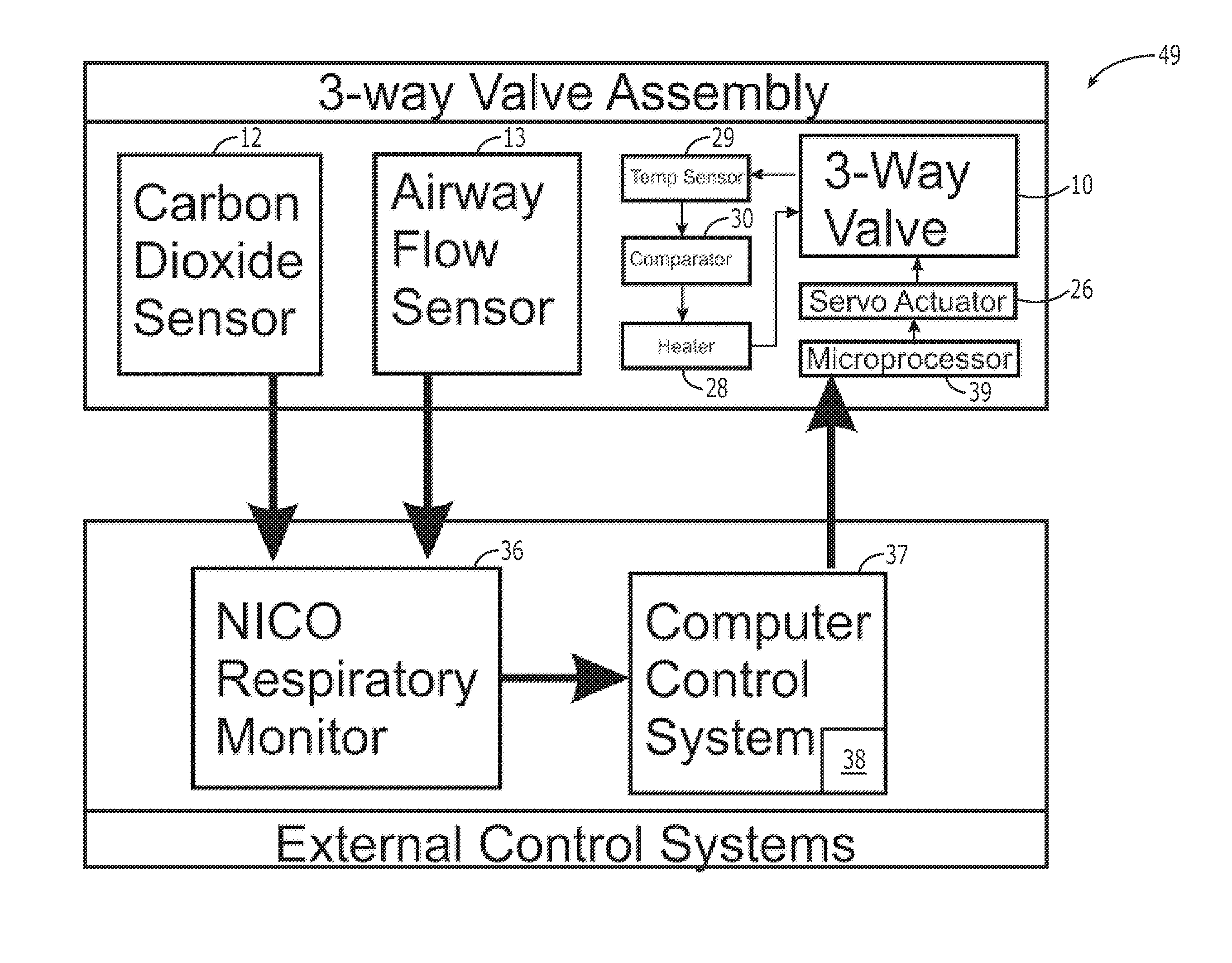
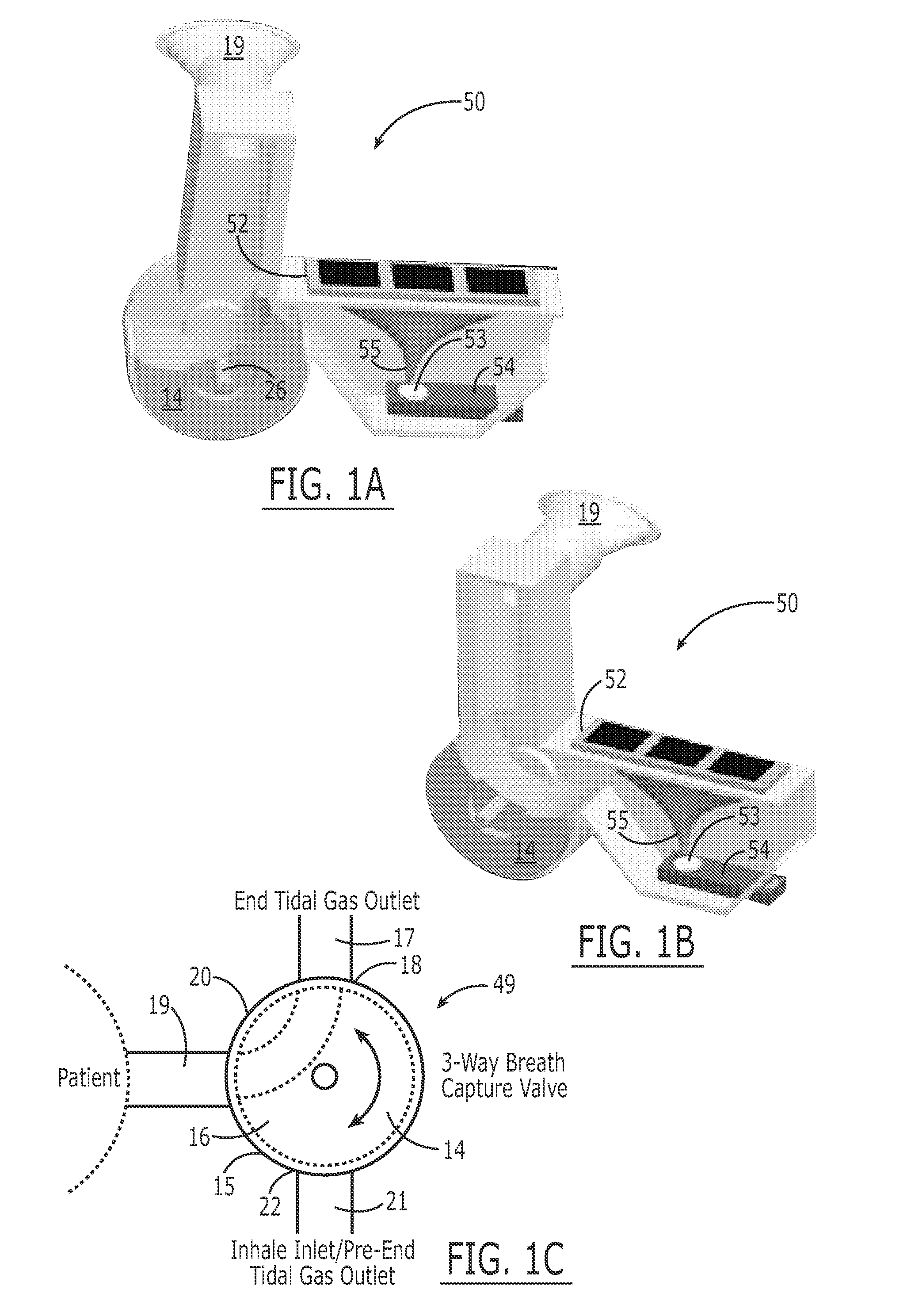
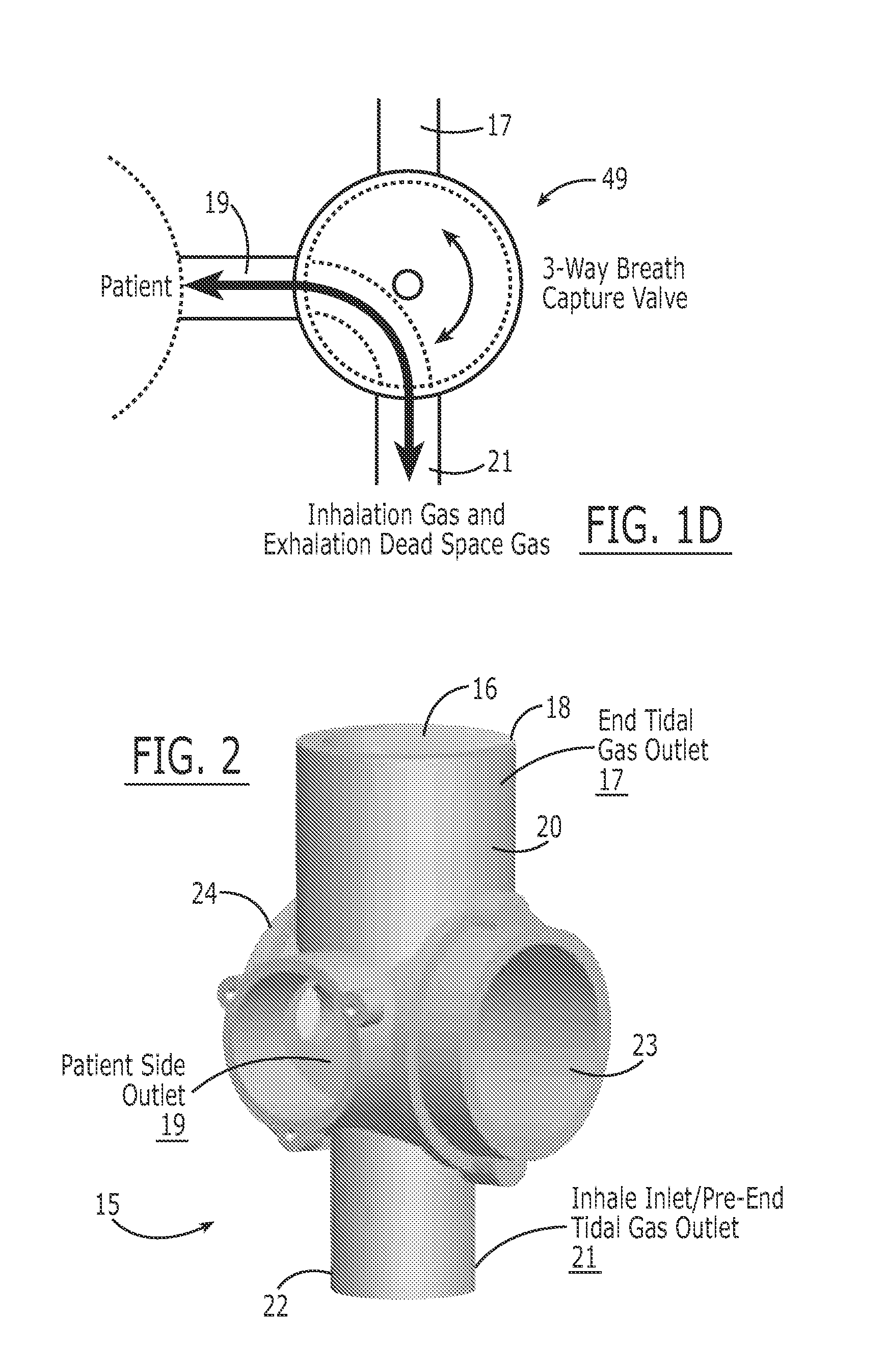
[0044]In a preferred embodiment of the invention, a system 10 for analyzing breath, breath aerosols, and breath condensate comprises a collection and analysis device 50 that is preferably disposable and is usable with a complementary electrical instrument housing 51, which may be non-disposable. The system 10 achieves automated extraction of condensate fluid from exhaled deep lung gas and immediate analysis by a miniaturized sensing system, such as that which may be implemented on a microfluidic device. The system 10 includes features for improved gas flow, condensate fluid extraction, and communication of the collected condensed fluid extract to the analysis system.

[0045]In the preferred embodiment of the invention, the automated provision of a drop of exhaled breath condensate to a miniaturized analysis device is accomplished by means of a Peltier cooler-ba...


PUM


Abstract

A system for collecting an exhaled breath sample and exhaled breath aerosol from a subject includes a condensation chamber having an outerwall defining an interior space. The outer wall has an inlet port and an outlet port therethrough in fluid communication with the interior space. The inlet port is placeable in fluid communication with an exhaled breath sample of the subject. A condensation element is positioned within the condensation chamber interior space and has a shape tapering downwardly toward a bottom tip thereof. A condensation of fluid on the condensation element is enhanced through various elements. A collection area is positioned within the condensation chamber's interior space beneath the condensation element bottom tip. The collection area is for collecting condensate accumulating on an outer surface of the condensation element and dropping from the tip thereof.

Description

CROSS-REFERENCE TO RELATED APPLICATION[0001]This application claims priority to provisional application Ser. No. 60 / 762,303, filed Jan. 26, 2007, entitled “Breath and Breath Condensate Analysis System and Associated Methods.”BACKGROUND OF THE INVENTION[0002]1. Field of the Invention[0003]The present invention relates to systems and methods for analyzing breath samples, and, more particularly, to such systems and methods for analyzing samples of breath condensate.[0004]2. Description of Related Art[0005]It is known in the art to analyze exhaled breath samples, for example, as a means to determine blood alcohol levels, and in anesthesia and critical care where inhalation anesthetic agents and exhaled carbon dioxide are routinely monitored. Infectious or metabolic diseases liberate specific odors that are characteristic of disease presence. Chromatographic techniques have identified volatile compounds in exhaled breath that can serve as potential markers for specific diseases. For exam...

Claims


Application Information

Patent Timeline
Patent Type & Authority Patents(United States)
IPC IPC(8): A61B5/08
CPCG01N33/497G01N35/1097
Inventor MEKA, VIKAS V.EULIANO, NEIL R.FLANAGAN, CRAIG T.LUTZ, BRENT JOSEPH
Owner EULIANO NEIL R
Learn More