
Variable flow computer cooling system for a data center and method of operation

a computer and cooling system technology, applied in the direction of lighting and heating apparatus, electrical equipment casings/cabinets/drawers, instruments, etc., can solve the problems of increasing the electrical power consumption of the cooling system and power conditioning required for the operation computer systems generating significant amounts of thermal energy, and the typical electrical efficiency of only 30% of the data center,

Active Publication Date: 2011-08-23
GLOBALFOUNDRIES US INC
View PDF45 Cites 25 Cited by
  • Summary
  • Abstract
  • Description
  • Claims
  • Application Information

AI Technical Summary

Benefits of technology

A data center is provided having a plurality of computer systems. Each of the computer systems has at least one processor, a plurality of electrical components and power electronics. A liquid cooling loop is fluidly coupled to each of the processors associated with said plurality of computer systems. The liquid cooling l

Problems solved by technology

During operation, the computer systems generate significant amounts of thermal energy.
However, the typical data center has an electrical efficiency of only 30% since the ancillary equipment needed for operations consume the remaining 70% of electrical power used by the data center.
Therefore, the cooling system and power conditioning required for the operation of the data centers will continue to consume an increasingly larger portion of the electrical power used by the data center.
Therefore, for a large portion of the time, the cooling system is under-utilized but still consuming a large amount of electrical power.
The size of the cooling system is further complicated by the thermal resistance between the computer system components, such as the processor for example, and the air.
As a result of the complexities of existing data center cooling systems, the data centers have considerable electrical power requirements.

Method used


Image

  • Variable flow computer cooling system for a data center and method of operation
  • Variable flow computer cooling system for a data center and method of operation
  • Variable flow computer cooling system for a data center and method of operation

Examples


Embodiment Construction

The use of the terms “a” and “an” and “the” and similar references in the context of describing the invention (especially in the context of the following claims) are to be construed to cover both the singular and the plural, unless otherwise indicated herein or clearly contradicted by context. The modifier “about” used in connection with a quantity is inclusive of the stated value and has the meaning dictated by the context (e.g., it includes the degree of error associated with measurement of the particular quantity). All ranges disclosed herein are inclusive of the endpoints, and the endpoints are independently combinable with each other.

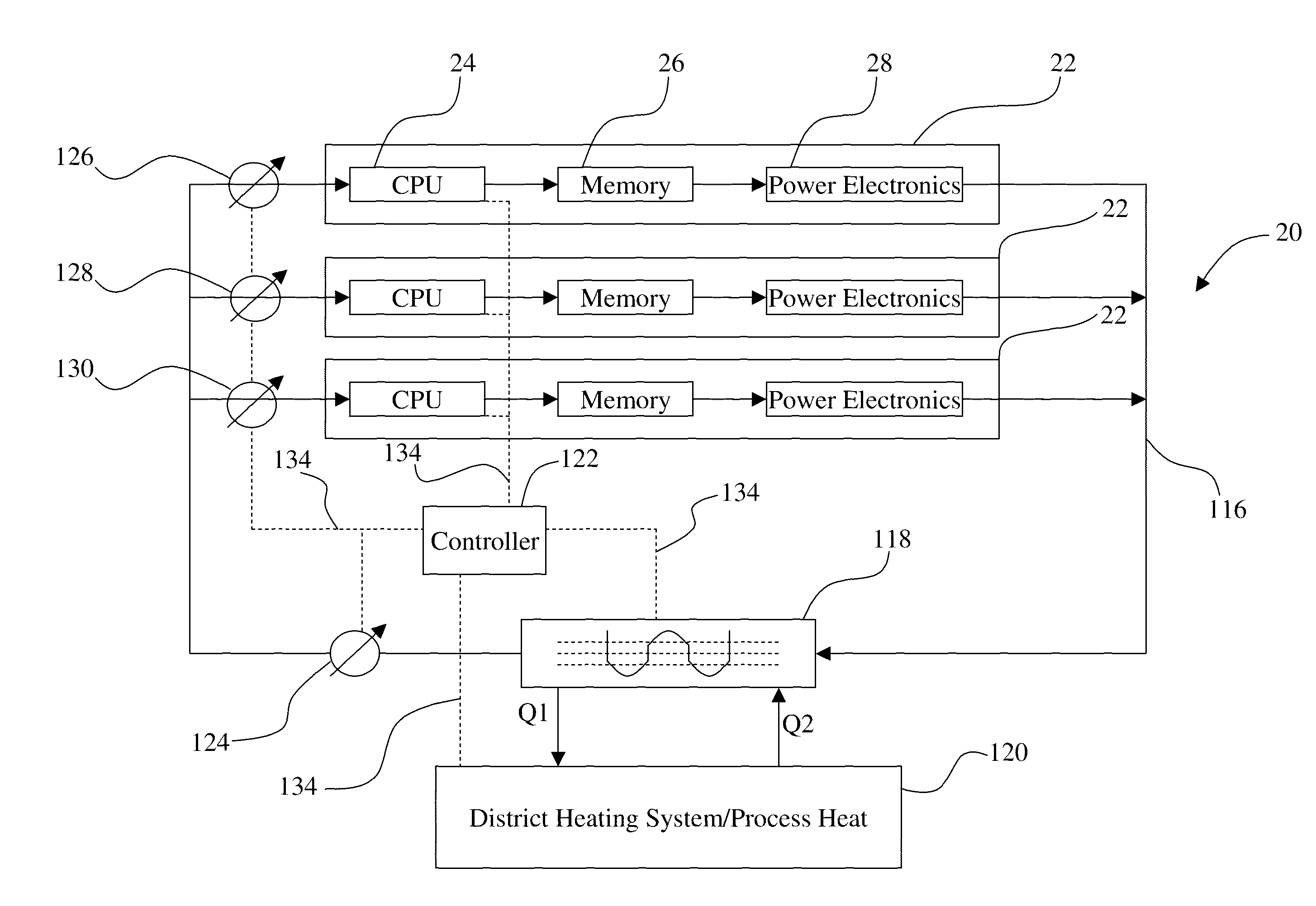
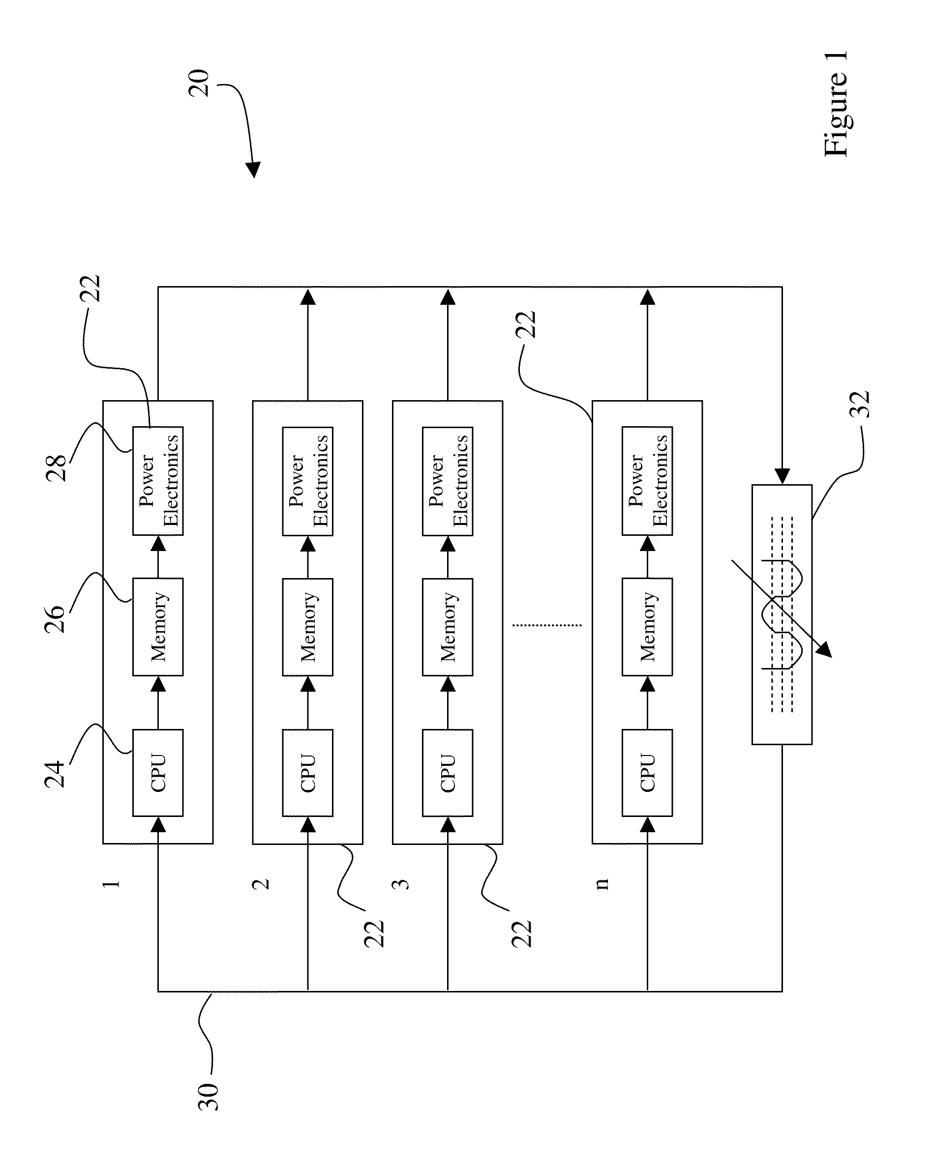
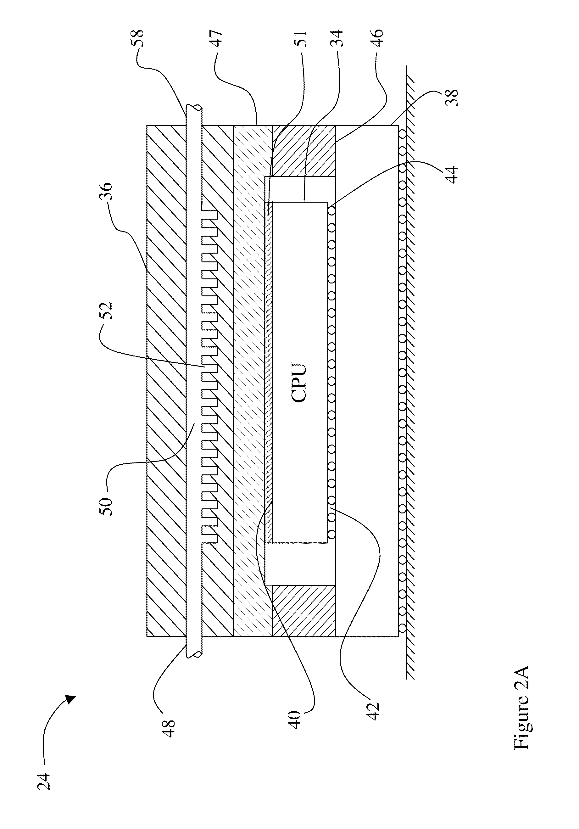
With reference now to FIG. 1 an exemplary depiction of a data center 20 is illustrated. The data center 20 includes a plurality of computer systems 22 that are arranged to provide computer-processing services. Each of the computer systems includes one or more processors 24 and the associated electronic components 26, such as random access memory or...


PUM


Abstract

Disclosed herein is a data center having a plurality of liquid cooled computer systems. The computer systems each include a processor coupled with a cold plate that allows direct liquid cooling of the processor. The cold plate is further arranged to provide adapted flow of coolant to different portions of the processor whereby higher temperature regions receive a larger flow rate of coolant. The flow is variably adjusted to reflect different levels of activity. By maximizing the coolant temperature exiting the computer systems, the system may utilize the free cooling temperature of the ambient air and eliminate the need for a chiller. A data center is further provided that is coupled with a district heating system and heat is extracted from the computer systems is used to offset carbon emissions and reduce the total cost of ownership of the data center.

Description

BACKGROUNDThis disclosure relates to a data center having liquid cooled computers and in particular to a data center having a cooling system that maximizes the coolant output temperature while maintaining a desired processor chip temperature.Data centers are facilities that house numerous computers systems. These computer systems are arranged to provide computer-processing services to users. Typically, the computer systems are arranged in racks that electrically connect the individual computers to the users and other computers. A standard size rack may accommodate up to 40 to 80 computer systems. The computer systems may include a number of components, including one or more processors, micro controllers, semiconductors, memory devices and the like. Each data center may have many racks of computer systems operating simultaneously.During operation, the computer systems generate significant amounts of thermal energy. Typically, each computer system may generate on the order of 200 W-25...

Claims


Application Information

Patent Timeline
IPC IPC(8): G06F1/20G05D23/19H05K7/20
CPCG06F1/20H05K7/20772Y10S165/908G06F2200/201
Inventor BRUNSCHWILER, THOMAS J.LINDERMAN, RYAN J.MICHEL, BRUNORUETSCHE, ERICH M.
Owner GLOBALFOUNDRIES US INC
Learn More