Device on a textile machine, especially a spinning preparation machine, for cooling heat-emitting electrical components

a technology of heat-emitting electrical components and textile machines, which is applied in the direction of safety devices for fibre treatment, continuous wounding machines, drafting machines, etc., can solve the problems of large heat generation, limited space available, and considerable increase, and achieve low maintenance and economic effects

Inactive Publication Date: 2011-08-30
TRUETZSCHLER GMBH & CO KG
View PDF17 Cites 6 Cited by
  • Summary
  • Abstract
  • Description
  • Claims
  • Application Information

AI Technical Summary

Benefits of technology

[0005]It is an aim of the invention to provide a device of the kind described at the beginning which avoids or mitigates the mentioned disadvantages and which, in particular, provides the necessary cooling in a structurally simple way and is also economical and low-maintenance.
[0009]2. because the cooling faces or elements around which the air flows can be suitably generously dimensioned, there is virtually no risk of unacceptable collection of lint, dust or the like;
[0010]3. the productivity of the machine, in the event of such contamination, can in some cases be considerably increased.

Problems solved by technology

On the other hand, however, that practice has the result that often only very limited space is available and so the switching devices usually have to be very closely and tightly packed into the switch cabinets.
As a result, generally a relatively large amount of heat is generated, which is often considerably increased by the unfavourable ambient temperatures in the spinning room preparation area.
The latter are generally ruled out from the outset on account of the considerable costs associated with their installation.
Unfortunately, such mats become clogged after a relatively short time so that the inflow or outflow of air is no longer sufficient.
The consequence is therefore frequent stoppages and machine downtimes caused by overheated switch cabinets or switching devices.
That exhaust air stream is freed of its impurities in a filter and in so doing increasingly clogging arises.
The cost of that device is high in terms of equipment.
A particular problem is that it is necessary to clean the filters in order to avoid or eliminate excessive heating.

Method used


Image

  • Device on a textile machine, especially a spinning preparation machine, for cooling heat-emitting electrical components
  • Device on a textile machine, especially a spinning preparation machine, for cooling heat-emitting electrical components
  • Device on a textile machine, especially a spinning preparation machine, for cooling heat-emitting electrical components

Examples


Embodiment Construction

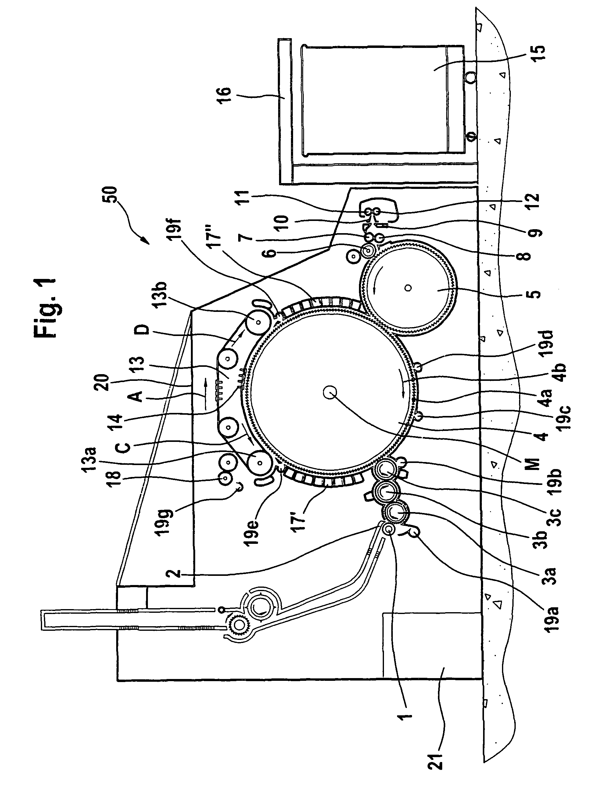
[0030]With reference to FIG. 1, a flat card 50, e.g. a TC 03 flat card, made by Trützschler GmbH & Co. KG of Mönchengladbach, Germany, has a feed roller 1, feed table 2, lickers-in 3a, 3b, 3c, cylinder 4, doffer 5, stripper roller 6, nip rollers 7, 8, web guide element 9, web funnel 10, delivery rollers 11, 12, revolving card top 13 with card top guide rollers 13a, 13b and flats 14, can 15 and can coiler 16. The directions of rotation of the rollers are indicated by curved arrows. Reference letter M denotes the centre point (axis) of the cylinder 4 and A indicates the working direction. Reference numeral 4a indicates the clothing and reference numeral 4b indicates the direction of rotation of the high-speed cylinder 4. Reference letter C indicates the direction of rotation of the revolving card top 13 in the carding position and reference letter D indicates the return transport direction of the flats 14. In the pre-carding zone, between the licker-in 3c and the rear card top guide r...


PUM

PropertyMeasurementUnit
temperatureaaaaaaaaaa
heataaaaaaaaaa
convective heataaaaaaaaaa

Abstract

In a device on a textile machine, for cooling heat-emitting electrical components, for example electrical switching devices and / or switch cabinets, the heat-emitting components are cooled by an air stream. In order to provide a device that ensures the necessary cooling in a structurally simple way and is economical and low-maintenance, at least one partial air stream of the supply air to the machine is guidable towards the heat-emitting components and the supply air is able to absorb heat from the components and subsequently flow via outlet through components of the textile machine.

Description

CROSS REFERENCE TO RELATED APPLICATION[0001]The present application claims priority from German Patent Application No. 10 2007 015 826.4 dated Mar. 30, 2007, the entire disclosure of which is incorporated herein by reference.BACKGROUND OF THE INVENTION[0002]The invention relates to a device on a textile machine, especially a spinning preparation machine, for cooling heat-emitting electrical components, for example electrical switching devices and / or switch cabinets.[0003]In the field of the textile industry, especially in the field of spinning room preparation, in modern machine designs the switch cabinets necessary for operating the machine are generally integrated directly into the machine or its frame. On the one hand, that has the advantage that the connections between sensors and actuators as well as the corresponding switching devices can be kept very short and simple. On the other hand, however, that practice has the result that often only very limited space is available and ...

Claims


Application Information

Patent Timeline
Patent Type & Authority Patents(United States)
IPC IPC(8): D01H11/00
CPCD01G15/00D01G15/12D01G15/32D01G31/00D01H1/16H01L23/467H05K7/20009H05K7/20145H05K7/20163
Inventor HOSEL, FRITZWIRTZ, DIETER
Owner TRUETZSCHLER GMBH & CO KG
Why Eureka
Try Eureka