Implantable prosthesis for positioning and supporting a breast implant

a breast implant and implantable prosthesis technology, applied in the field of implantable prosthesis for positioning and supporting breast implants, can solve the problems of increased risk of capsular contracture, increased visibility and vulnerability of implants, visible implant rippage, etc., to facilitate tissue growth and secure the fixation of implantable prosthesis.

Active Publication Date: 2011-08-30
LIFECELL
View PDF27 Cites 61 Cited by
  • Summary
  • Abstract
  • Description
  • Claims
  • Application Information

AI Technical Summary

Problems solved by technology

The downsides of this placement are increased chances for capsular contracture, greater visibility and vulnerability for the implant.
This alternative reduces the risk of capsular contracture and visible implant rippling, but recovery time from this positioning is typically longer and more painful because the surgeon has to manipulate the muscle during surgery.
Also, because of increased swelling, the implant may take longer to drop into a natural position after surgery.
This placement has even longer recovery time, potential loss of inferior pole fullness, and involves a more traumatic surgical procedure.
The transaxillary incision is rarely reused because it is difficult to work on an implant from what is really a remote site.
Visibility inside the breast is extremely limited for the surgeon with a transaxillary incision without the use of a fiber optic endoscope, which can be cumbersome in a revisional setting.
Presently, there are very few techniques to reliably maintain the position of implants placed as part of cosmetic or reconstructive surgical procedures.
Implant malposition may be the result of several factors, including poor surgical technique, i.e. the implant pocket is too big or too low; implant weight; or lack of soft tissue support.
In addition, in reconstructive patients cancer treatments, such as chemotherapy, weaken the soft tissue and surgery, in general, interrupts the natural anatomic plains of the soft tissue.
Such situations typically provide extremely poor soft tissue support and the inability of the usual support structures within the breast, such as the inframammary fold, to support the weight of the implant.
The condition is most often related to technical error by a surgeon attempting to create too much cleavage in the patient or using an overly wide implant.
Lateral displacement results in the implant moving into the armpit, especially when the patient is lying flat on her back.
Lateral displacement is most common with submuscular placement when muscle is inadequately released medially and is the most under-recognized implant displacement problem.
Bottoming out of implants may be exacerbated by a failure to wear a bra, activities resulting in excessive “bouncing” of the implants, excessively large implants, and / or extreme weight loss.
Once these problems are established, classical repair techniques have had limited effectiveness, with high rates of displacement recurrence.
The problems with this method are numerous.
First, the scar capsule is often attenuated making adequate “bites” of capsule impossible.
Second, the capsule is itself distensible so the factors which initially acted on the pocket can result in rapid recurrence.
Finally, and most obviously, in nearly all cases the implant is replaced once the repair is complete—once again putting strain on the repair especially in the case of bottoming out.
These bolsters may limit direct implant pressure but leave unattractive scars on the skin due to the tension.
For medial malposition, the use of a Thongbra® (a bra designed to apply pressure over the sternum) or bolsters placed to secure the medial breast skin to the underlying sternum have had limited success.

Method used


Image

  • Implantable prosthesis for positioning and supporting a breast implant
  • Implantable prosthesis for positioning and supporting a breast implant
  • Implantable prosthesis for positioning and supporting a breast implant

Examples


Embodiment Construction

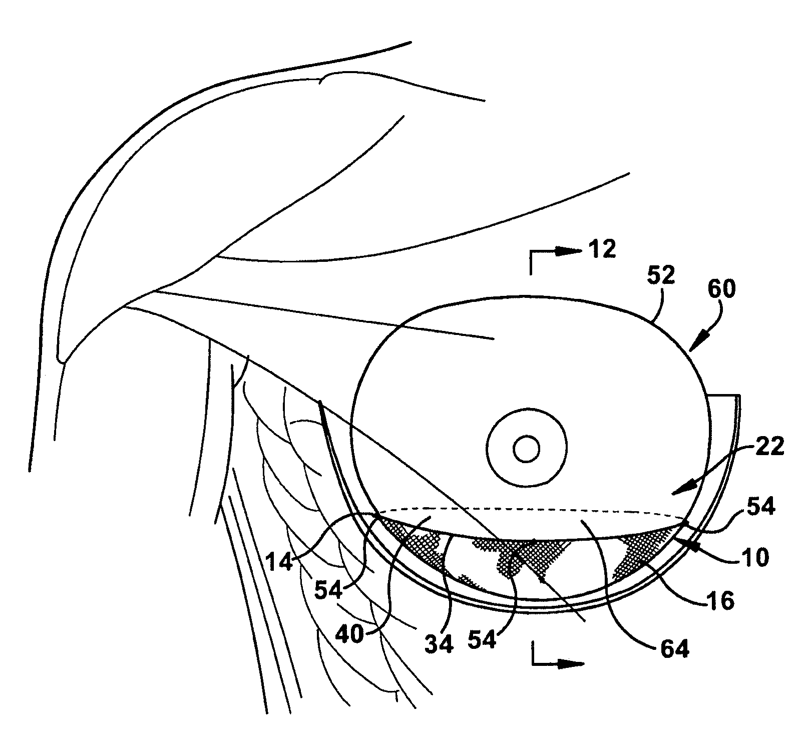
[0035]The current innovation calls for the development of an implantable prosthesis in the form of a support sling for use in cosmetic and reconstructive breast surgery. This implantable prosthesis would not be used to hold native breast tissue in place but rather to minimize the amount of implant displacement. Most implants placed for reconstruction and augmentation are placed in the sub-muscular position. From this position, an implantable prosthesis placed medially, laterally, or inferiorly would be in contact solely with the muscles of the chest wall and would not be directly in contact with breast parenchyma.

[0036]The implantable prosthesis of the present invention can be utilized during corrective procedures to reposition a malpositioned implant or as a prophylactic measure during procedures wherein the implant is initially placed and positioned within the patient. As is shown, in FIGS. 5 and 6, the implantable prosthesis 10 comprises a sheet 12 of prosthetic material, which i...


PUM


Abstract

An implantable prosthesis for use in positioning a breast implant comprising a sheet of a prosthetic material configured to form a sling-shaped receiving area for receiving and supporting the breast implant. The surface area of the implantable prosthesis contacting the breast implant comprises a biocompatible or chemically inert material to prevent abrasion of or reaction with the breast implant. The implantable prosthesis of the present invention can be used during corrective procedures to reposition and support a malpositioned breast implant or during reconstructive or cosmetic procedures at the time the implant is first positioned within the patient. The prosthesis is used with implants in the partial sub-muscular, completely sub-muscular, and sub-glandular position and is used to prevent medial, lateral and inferior displacement of the implant.

Description

CROSS-REFERENCE TO RELATED APPLICATIONS[0001]This application is a continuation-in-part of U.S. patent application Ser. No. 11 / 196,217, filed on Aug. 3, 2005, which claims priority to U.S. Provisional Patent Application Ser. No. 60 / 599,512, filed on Aug. 6, 2004.BACKGROUND OF INVENTION[0002]1. Field of Invention[0003]The present invention relates to an implantable prosthesis for positioning and supporting a breast implant within a patient and a method of positioning and supporting the breast implant within the patient using the implantable prosthesis.[0004]2. Description of Related Art[0005]The American Society of Plastic Surgeons reports that breast augmentation procedures increased seven-fold in the ten-year period between 1992 and 2002, increasing from 32,607 procedures in 1992 to 225,818 procedures in 2002. Overall it has been estimated from breast implant sales data that anywhere between 1.5 to more than 2 million women in the United States alone have breast implants. An estima...

Claims


Application Information

Patent Timeline
Patent Type & Authority Patents(United States)
IPC IPC(8): A61F2/12
CPCA61F2/12
Inventor FRANK, ROBERT E.
Owner LIFECELL
Why Eureka
Try Eureka