
Non-rotating breast implant

a breast implant and non-rotating technology, applied in the field of breast implants, can solve the problems of inability to rotate implants, inconvenient deformation, and very distinct disadvantages of textured implants, and achieve the effect of natural appearance and feel, less of a tendency to wrinkle or rippl

Inactive Publication Date: 2006-09-12
BELLIN HOWARD T
View PDF22 Cites 45 Cited by
  • Summary
  • Abstract
  • Description
  • Claims
  • Application Information

AI Technical Summary

Benefits of technology

[0020]An advantage of the present invention is that anatomical-shaped breast implants are held in position, with their superior poles correctly oriented in the superior position without slippage or spin off in the medial or lateral directions.

Problems solved by technology

A problem with anatomical implants is that if the outer surface of the implant is smooth, the implant can rotate.
This creates an unacceptable deformity.
Textured implants have a very distinct disadvantage, however.
The problem is that textured implants have a tendency to ripple (i.e. produce a folding, wrinkling or waviness on the surface of the implant).
Rippling creates an extremely unsatisfactory appearance.
Rippling—visible or palpable waviness on the implant surface—is one of the major problems with breast implants.
This folding of the implant can often be felt or seen and can be extremely obtrusive.
Therefore, to solve the problem of implant rotation with texturing the entire implant as is presently done, one must compound the problem of severe, unacceptable rippling.

Method used


Image

  • Non-rotating breast implant
  • Non-rotating breast implant
  • Non-rotating breast implant

Examples


Embodiment Construction

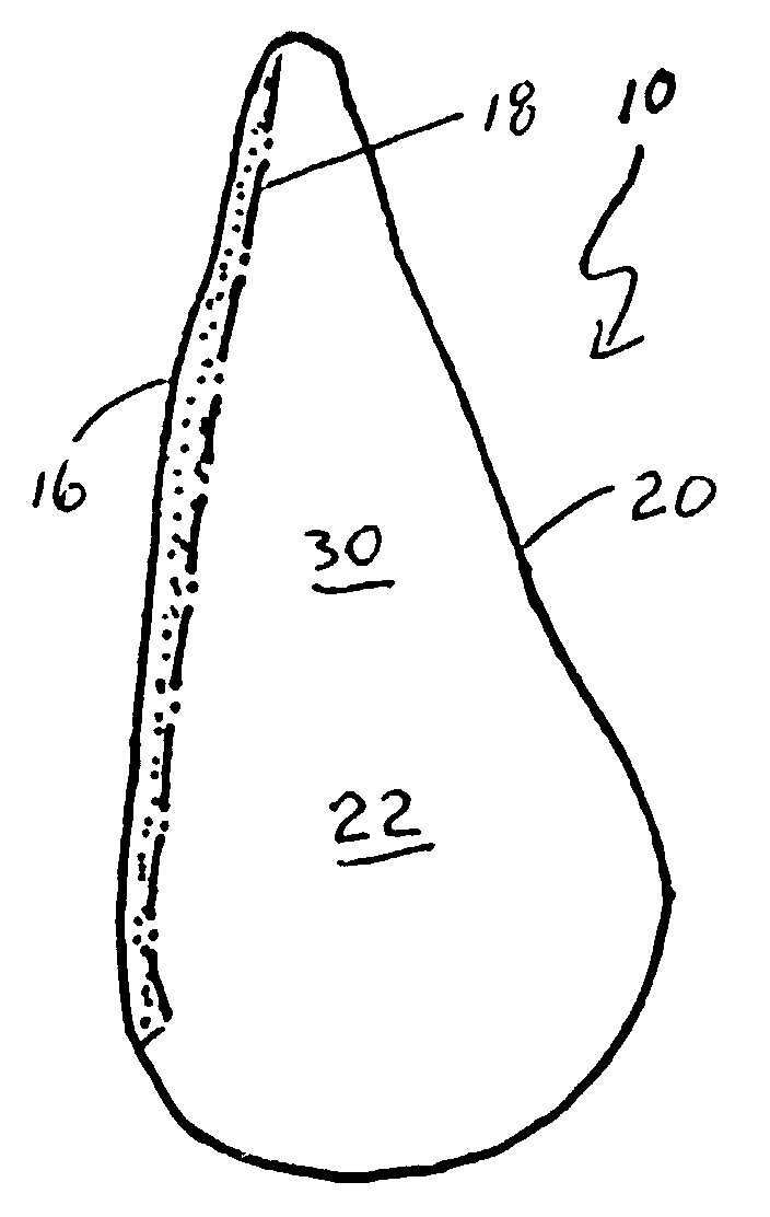
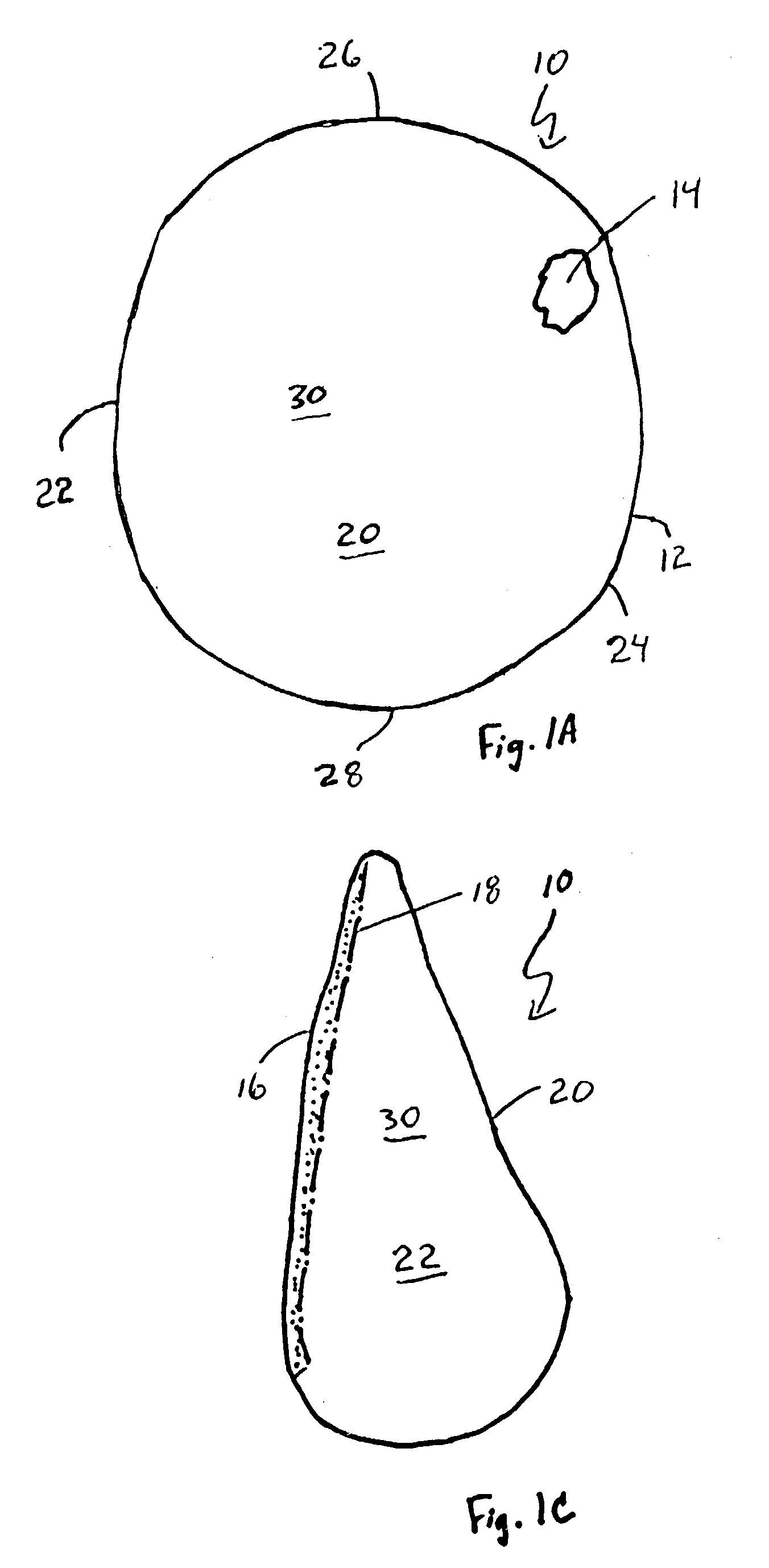
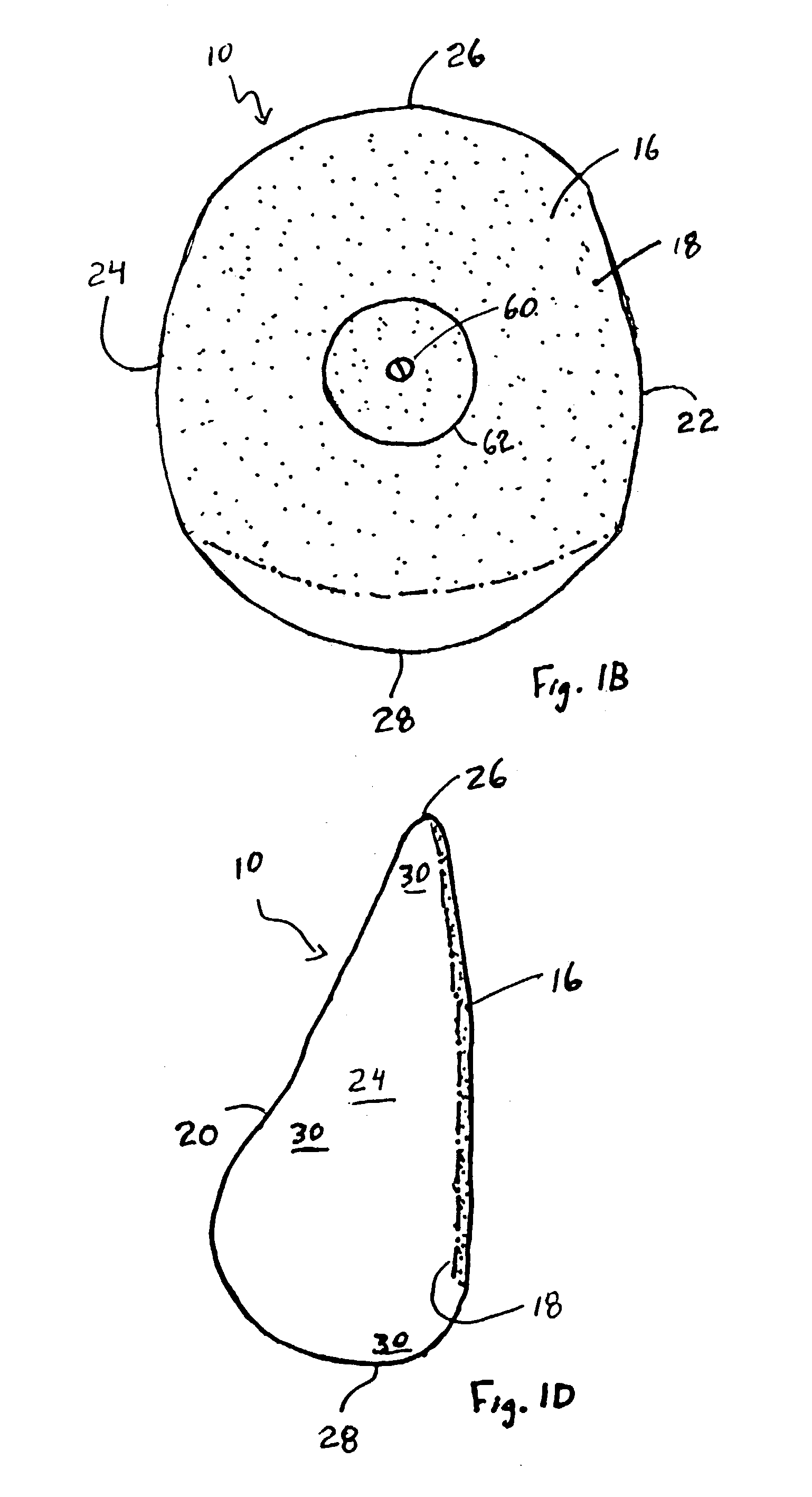
[0040]As shown in FIGS. 1A–D and 3A, an anatomical-shaped breast implant is designated in general by reference number 10. The implant 10 includes an envelope 12 and fill material 14 sealed in the envelope 12. The envelope 12 further includes a posterior (rear) side or face 16 that includes a textured or relatively rough surface 18 and an anterior (front) side or face 20 that is smooth or relatively smooth compared to the relatively rough surface 18. The envelope 12 further includes a right side 22 (shown in FIG. 1C) and a left side 24 (shown in FIG. 1D). Depending upon the breast into which the implant 10 is implanted, the right side 22 may be the medial or lateral side of the implant 10 and the left side 24 may be the medial or lateral side of the implant 10. The implant 10 further includes a superior (upper) pole 26 and an inferior (lower) pole 28. The anterior (front) side 20 of the envelope 12 has a smooth surface 30, relatively thin wall 32 and is cured once (though subject twi...


PUM

PropertyMeasurementUnit
thicknessaaaaaaaaaa
thicknessaaaaaaaaaa
thickaaaaaaaaaa

Abstract

A non-rotating anatomical-shaped breast implant having a front side with a smooth surface and a rear side with a textured surface. A smooth surface ripples or wrinkles little, if at all. Rippling or wrinkling of the implant may undesirably produce a visible or palpable waviness on the skin of the breast. A smooth surface is more likely to produce the look and feel of a natural breast. A rear side with a textured surface is desirable because tissue growth of the body, after the implant has been implanted, engages the textured surface to anchor the implant in place such that the front side with the smooth surface remains matched with the front side of the body and such that the anatomical-shaped breast implant with its tear drop shaped fullness remains at a natural position within the breast. The disclosure further includes a method for minimizing the rotation of an implant within the body and a method for making an implant envelope that has different thicknesses.

Description

[0001]This application is a divisional of application Ser. No. 09 / 452,656 filed on Dec. 1, 1999, now U.S. Pat. No. 6,692,527.BACKGROUND OF THE INVENTION[0002]The present invention relates generally to implants for the body and particularly to implants that have features that minimize or prevent rotation of an implant in a body. More specifically, the present invention is a breast implant that has an anatomical shape that gives a more natural look to the augmented breast, but cannot rotate because it has a texturing on the back that anchors it, yet is smooth on the surface to minimize rippling.[0003]The preferred shape for an implant used for cosmetic breast augmentation is the so-called “anatomical shape” that is also referred to as “tear drop.” This shape has more of the substance filling the silicone elastomer shell in the inferior pole of the implant and less in the superior pole, thus mimicking the natural shape of the breast. For a given volume, round shaped implants have too m...

Claims


Application Information

Patent Timeline
Patent Type & Authority Patents(United States)
IPC IPC(8): B29C35/02B29C41/14A61F2/00A61F2/12
CPCA61F2/12B29C41/14A61F2/0077B29L2031/7532B29C2791/001B29C37/0053
Inventor BELLIN, HOWARD T.KREDOVSKI, KENNETH C.CAMPBELL, RUAIRIDH W.
Owner BELLIN HOWARD T
Learn More