Mobile radar and planar antenna
a planar antenna and mobile technology, applied in direction finders using radio waves, multi-channel direction-finding systems using radio waves, instruments, etc., can solve the problem of high accuracy in azimuth angle detection of obstacles, one of the challenges, and achieve wide azimuth detection range and high resolution performance
- Summary
- Abstract
- Description
- Claims
- Application Information
AI Technical Summary
Benefits of technology
Problems solved by technology
Method used
Image
Examples
first embodiment
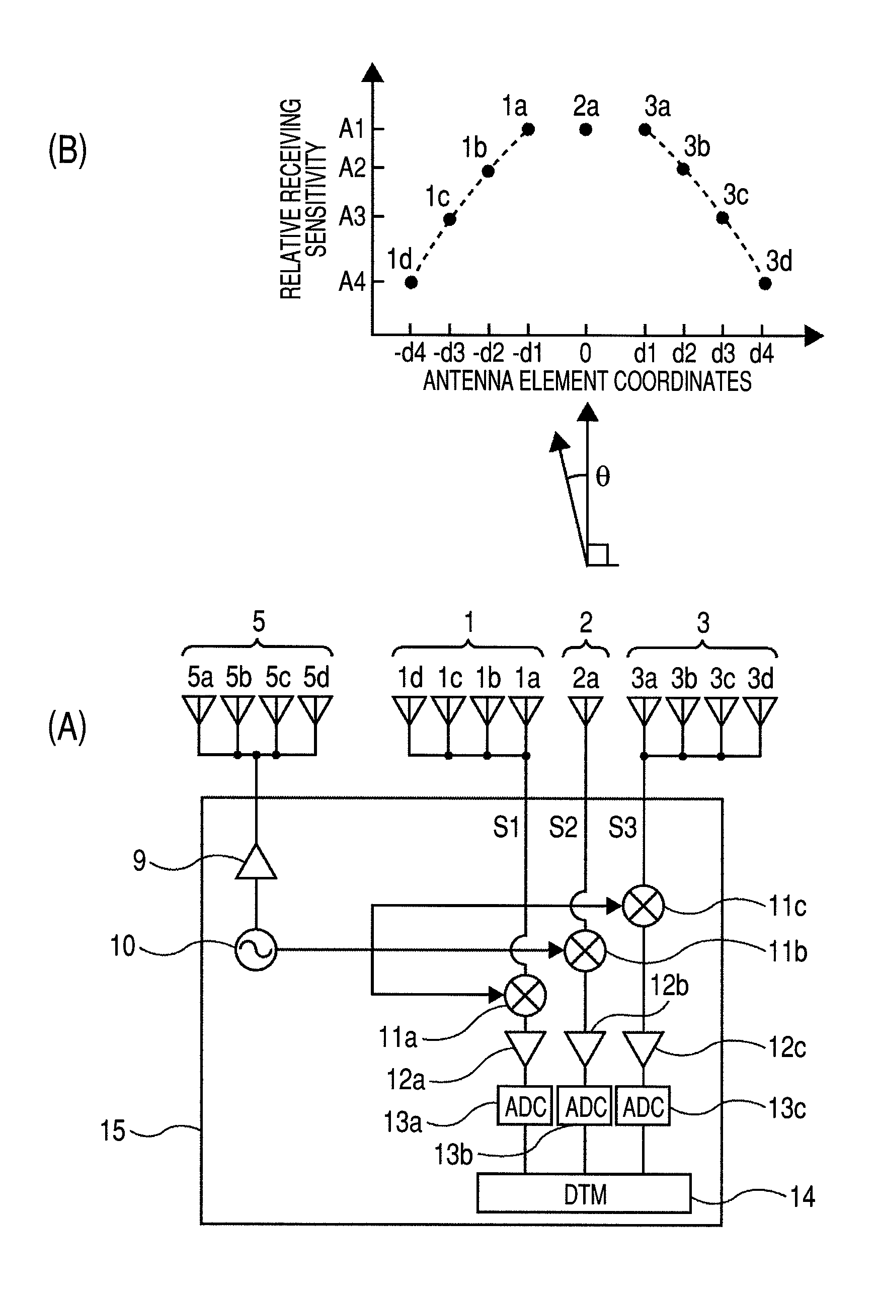
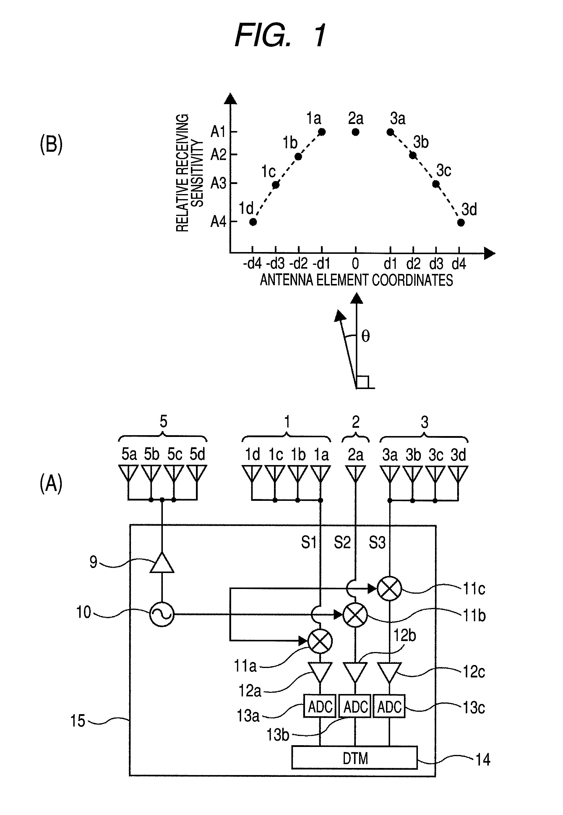
[0052]First, a first embodiment of the present invention will be described with reference to FIGS. 1 to 6. In FIG. 1, (A) is a conceptual diagram showing the configuration of a mobile radar according to the first embodiment. (B) of FIG. 1 is a diagram showing a relationship between antenna element coordinates and a relative receiving sensitivity of the mobile radar shown in (A) of FIG. 1.
[0053]In (A) of FIG. 1, the automotive radar includes a planar antenna having one transmitting array antenna 5 and three receiving array antennas 1, 2, and 3, and a transmitter-receiver unit 15. A radio wave transmitted from the transmitting array antenna is reflected by at least one obstacle and received by the receiving array antennas 1, 2, and 3, as a receive signal. The receiving array antennas 1, 2, and 3 of the planar antenna are aligned in a horizontal direction. Symbol θ represents an azimuth angle.
[0054]A millimeter wave signal generated by an oscillator 10 of the transmitter-receiver unit ...
second embodiment
[0099]In the first embodiment of the present invention, plural receiving array antennas are divided into two (right and left) groups with one receiving array antenna as a center. Alternatively, a boundary line may be defined between two receiving array antennas to divide plural receiving array antennas into two (right and left) groups.
[0100]FIG. 8 is a configuration diagram showing a mobile radar according to a second embodiment of the present invention. (A) of FIG. 8 is a conceptual diagram showing the configuration of the mobile radar according to the second embodiment, and (B) is a diagram showing a relationship the antenna element coordinates and the relative receiving sensitivity of the mobile radar shown in (A) of FIG. 8. A millimeter wave signal generated by the oscillator 10 is added to the transmitting array antenna 5 through the power amplifier 9. The transmit signal radiated from the transmitting array antenna 5 is reflected by the obstacle, and received by the receiving ...
third embodiment
[0107]The present invention can be applied to a case where four or more constant-velocity obstacles is to be separated and detected, that is, a case where five or more receiving array antennas are necessary.
[0108]FIG. 9 is a configuration diagram showing a mobile radar according to a third embodiment of the present invention. (A) of FIG. 9 is a conceptual diagram showing the configuration of the mobile radar according to the third embodiment, and (B) of FIG. 9 is a diagram showing a relationship between the antenna element coordinates and the relative receiving sensitivity of the mobile radar shown in (A). The transmitting array antenna 5, and the receiving array antennas 1, 2, 6, 4, and 3 are composed of the antenna elements 5a to 5d, 1a to 1d, 2a, 6a, 4a, and 3a to 3d, respectively, and aligned in the horizontal direction. Similarly, in this embodiment, the number (four in this embodiment) of antenna elements of the receiving array antennas 1 and 3 at both outer ends thereof which...
PUM
 Abstract
Description
Claims
Application Information
 - R&D
- Intellectual Property
- Life Sciences
- Materials
- Tech Scout
- Unparalleled Data Quality
- Higher Quality Content
- 60% Fewer Hallucinations
Browse by: Latest US Patents, China's latest patents, Technical Efficacy Thesaurus, Application Domain, Technology Topic, Popular Technical Reports.
© 2025 PatSnap. All rights reserved.Legal|Privacy policy|Modern Slavery Act Transparency Statement|Sitemap|About US| Contact US: help@patsnap.com


