Digital polar transmitter

a digital polar transmitter and transmitter technology, applied in pulse technique, dc level restoring means or bias distortion correction, baseband system details, etc., can solve the problems of reducing the efficiency of the nonlinear device, affecting the operation efficiency, and affecting the quality of the waveform,

Active Publication Date: 2011-08-30
EAGLE TECH LLC
View PDF56 Cites 23 Cited by
  • Summary
  • Abstract
  • Description
  • Claims
  • Application Information

AI Technical Summary

Problems solved by technology

However, some nonlinear devices operate more efficiently when the output response is nonlinear—for example, when a power amplifier approaches saturation.
As a result, there is often a tradeoff between waveform quality and efficiency.
For example, when a nonlinear device approaches saturation or starts to exhibit nonlinear qualities (which may improve efficiency), the waveform quality may be degraded and may not meet the specific requirements and standards.
Alternatively, if nonlinear devices are set to operate in linear regions to meet quality standards or requirements, then power consumption and current drain may be degraded because the device is operating at a lower efficiency level.
Correction of the nonlinearity of the power amplifier becomes extremely challenging as the polar modulation technique is applied to non-constant envelope modulation.
Open-loop correction, which typically involves a lookup table (LUT) is relatively simple, but needs significant manufacturing calibration for collecting tables or calculating the coefficients, and suffers performance loss if the device nonlinearity varies once out of the manufacturing environment and the pre-collected tables or pre-calculated coefficients are no longer accurate enough.
On the other hand, error-based closed-loop correction, either adaptive or non-adaptive, may fail to deliver accurate correction to severe nonlinearities, especially for a high gain loop with large delay.

Method used


Image

  • Digital polar transmitter
  • Digital polar transmitter
  • Digital polar transmitter

Examples


Embodiment Construction

[0022]The term “signal,” as used herein, should be broadly construed to include any manner of conveying data from one place to another, such as, for example, an electric current or electromagnetic field, including without limitation, a direct current that is switched on and off or an alternating-current or electromagnetic carrier that contains one or more data streams. Data, for example, may be superimposed on a carrier current or wave by means of modulation, which may be accomplished in analog or digital form. The term “data” as used herein should also be broadly construed to comprise any type of intelligence or other information, such as, for example and without limitation, audio, video, and / or text information.

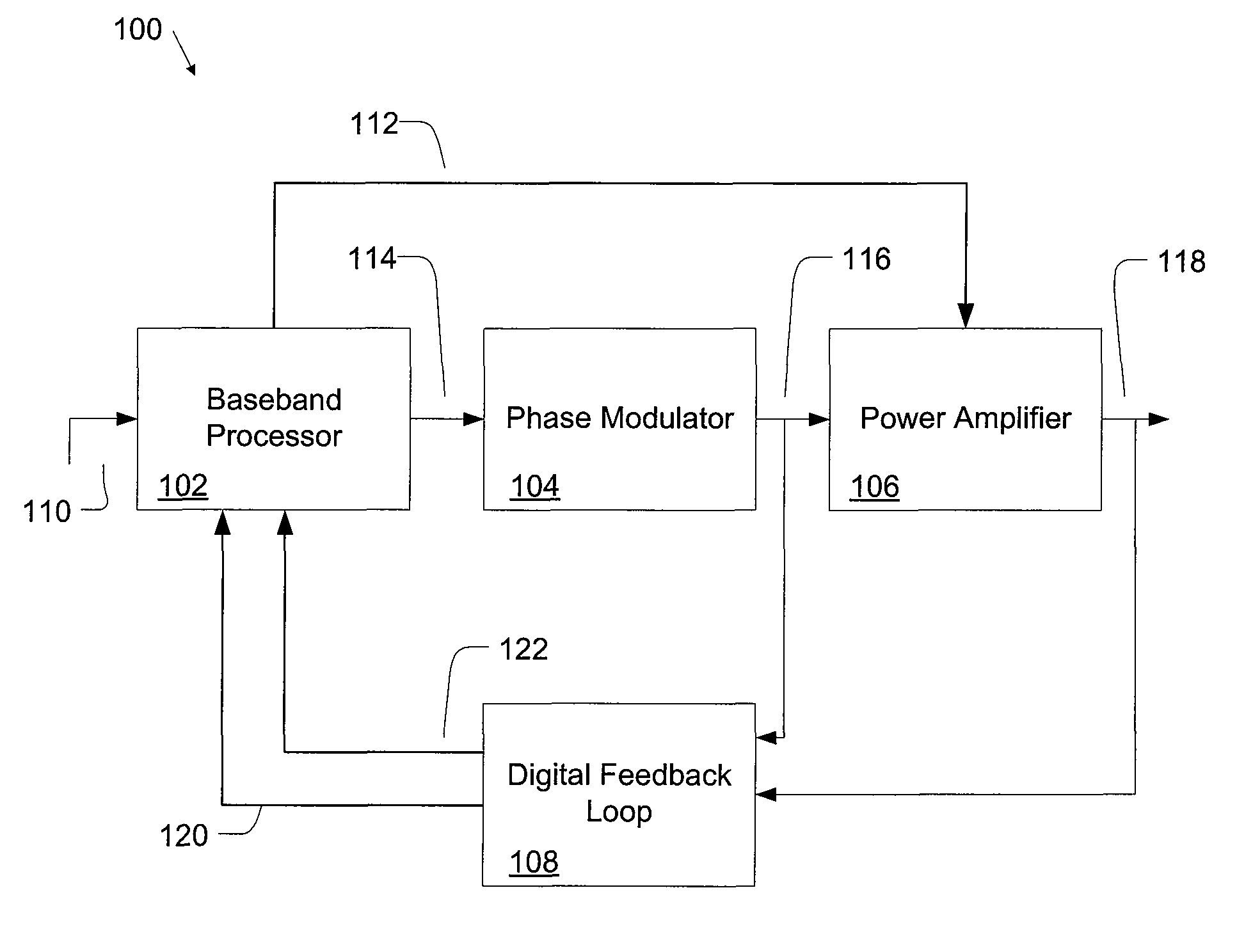
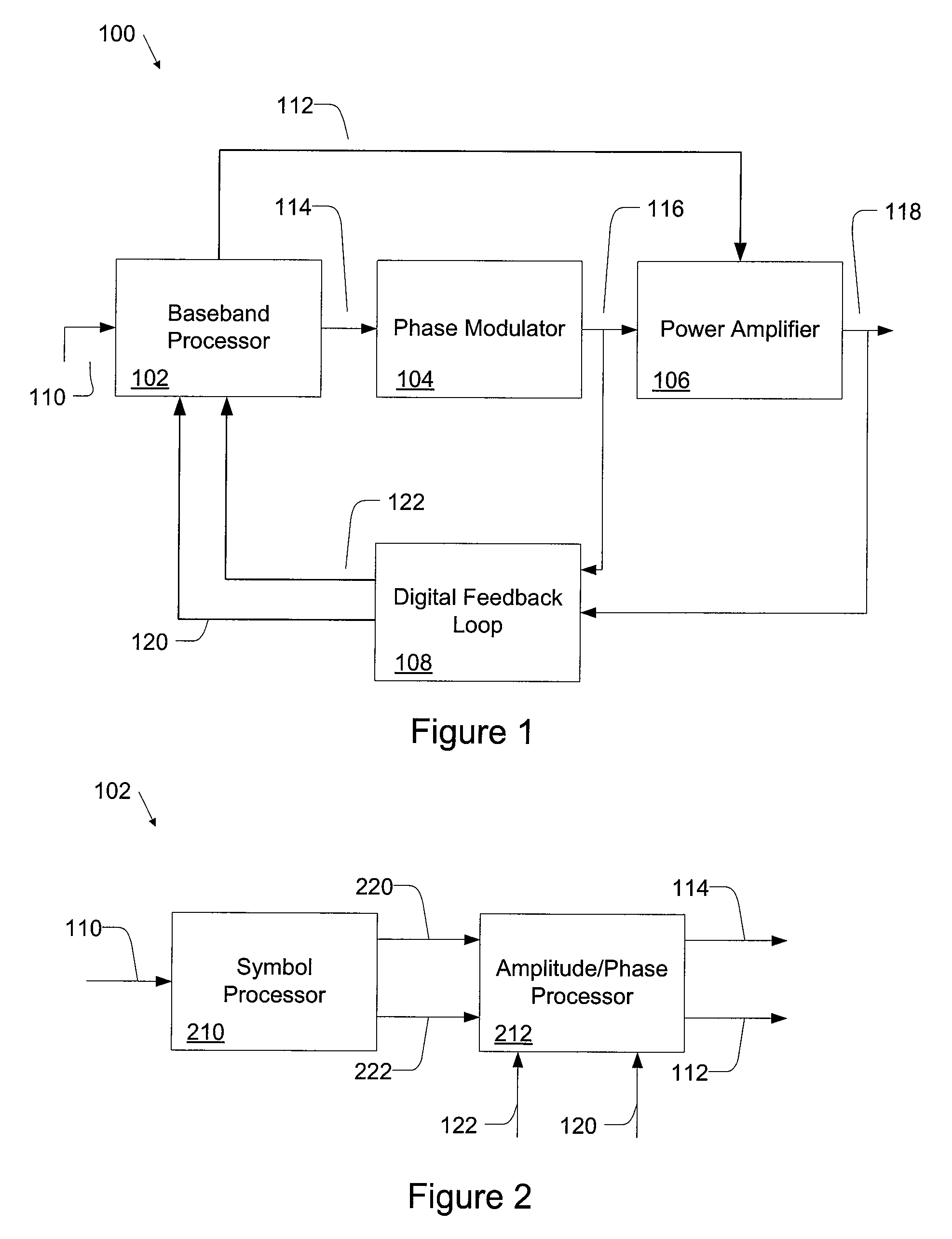
[0023]FIG. 1 is a block diagram of a digital polar transmitter 100. The transmitter 100 includes a baseband processor 102, a phase modulator 104, a power amplifier module 106, and a digital feedback loop 108.

[0024]The baseband processor 102 receives a digital input signal 1...


PUM


Abstract

A digital polar transmitter includes a baseband processor configured to receive an input signal and to convert the input signal into a baseband amplitude component and a baseband phase component. The transmitter also includes a phase modulator in communication with the baseband processor. The phase modulator is configured to modulate an RF carrier signal based on the phase component and to generate a phase-modulated RF carrier signal. A power amplifier is provided in communication with the baseband processor and the phase modulator. The power amplifier is configured to amplify the phase-modulated RF carrier signal based on the baseband amplitude component and to generate an amplified RF signal. The transmitter also includes a digital feedback loop in communication with the power amplifier and the baseband processor. The digital feedback loop is configured to detect the amplified RF signal and to provide a digital amplitude feedback signal and a detected phase feedback signal to the baseband processor.

Description

CLAIM OF PRIORITY[0001]This application claims the benefit of the U.S. provisional application 60 / 906,924, filed on Mar. 13, 2007, which is hereby incorporated by reference.FIELD OF THE INVENTION[0002]This invention relates to wireless transmission, and specifically to digital polar transmission.BACKGROUND OF THE INVENTION[0003]Polar modulation is a technique where a signal, or carrier, having constant radian frequency ω, is time-varied in both magnitude and phase. Polar modulation transmitters transmit information that both the magnitude (R) and the phase (θ) of a signal carry simultaneously. There are many benefits to using polar modulation to transmit information, particularly for wireless handset transmitter designs. Polar transmitters may receive baseband signals represented in Cartesian form as an in-phase (I) component and a quadrature (Q) component. An IQ baseband signal may be converted to polar form in terms of its magnitude R and phase θ signals. The magnitude R is referr...

Claims


Application Information

Patent Timeline
Patent Type & Authority Patents(United States)
IPC IPC(8): H04K1/02
CPCH03C5/00H03K7/10H04L25/06H04L27/34H04L27/361H04L27/3863H04L27/389
Inventor AHMED, WALID KHAIRY MOHAMEDLI, QINGREDDY, AJIT KUMARCAREY, EOIN
Owner EAGLE TECH LLC
Why Eureka
Try Eureka