Vehicle controller and control method

a technology of vehicle controller and control method, which is applied in the direction of process and machine control, brake system, instruments, etc., can solve the problem of unnecessary limitation of the increase of driving force, and achieve the effect of improving the starting characteristi

Inactive Publication Date: 2011-08-30
TOYOTA JIDOSHA KK
View PDF10 Cites 4 Cited by
  • Summary
  • Abstract
  • Description
  • Claims
  • Application Information

AI Technical Summary

Benefits of technology

[0009]The present invention was made in view of the foregoing and its object is to provide, in a vehicle having the brake hold function, a controller and a control method that can improve starting characteristic when the brake hold control is released.
[0011]According to the present invention, while the brake hold control is being executed, creep force of the vehicle is stopped until the degree of acceleration request by the driver (for example, actual accelerator pedal position) exceeds the second degree smaller than the first degree, in order to reduce unnecessary energy consumption. The creep force refers to the driving force for moving the vehicle forward at slow speed, even in a state in which the accelerator pedal is not operated, or almost not operated. If the degree of acceleration request exceeds the second degree thereafter, the creep force is recovered even if brake hold control is continued. Therefore, by the time the degree of acceleration request attains to the first degree and the brake hold control is released, a torque corresponding to the creep force has already been acting on the vehicle drive line, in a direction of moving the vehicle forward. Therefore, when the brake hold control is released and the driving force is increased, the direction of torque acting on the drive line is not changed. As a result, it becomes unnecessary to limit the amount of increase of the driving force per unit time. As compared with the recovery of creep force at the time of releasing brake hold control, the amount of increase of the driving force per unit time can be made larger. As a result, for a vehicle having the brake hold control function, a controller is provided that can improve starting characteristic when the brake hold control is released.
[0013]According to the present invention, when the creep force is recovered, the creep force attains to the maximum in a period from the start of recovery of the creep force to the release of brake hold control. Therefore, starting characteristic at the time of releasing the brake hold control can be improved. In addition, as the creep force increases more moderately than when the creep force is maximized immediately after recovery of the creep force (that is, when the degree of acceleration request exceeds the second degree), abrupt change in torque applied to the drive line can be prevented.
[0015]According to the present invention, when the creep force is recovered, the creep force is increased in accordance with the degree of acceleration request by the driver (for example, actual accelerator pedal position). By such an approach, unnecessary energy can be reduced by making the creep force smaller when, for example, the degree of acceleration request is low. Further, the creep force is increased to be closer to the maximum value as the degree of acceleration request comes closer to the first degree, to be ready for the release of brake hold control. Therefore, starting characteristic when the brake hold control is released can be improved. In addition, as the creep force increases more moderately than when the creep force is maximized when the degree of acceleration request exceeds the second degree, abrupt change in torque applied to the drive line can be prevented.
[0016]More preferably, the control unit calculates a creep torque reflection ratio based on a state of the vehicle, calculates a requested driving force of the vehicle based on the creep torque reflection ratio, controls driving force of the vehicle based on the requested driving force, limits the requested driving force until the requested driving force exceeds a predetermined value, stops the creep force by setting the creep torque reflection ratio to approximately zero until the degree of acceleration request exceeds the second degree, and increases the creep torque reflection ratio when the degree of acceleration request exceeds the second degree, thereby to recover the creep force.
[0017]According to the present invention, until the requested driving force calculated based on the creep torque reflection ratio exceeds a predetermined value, the requested driving force is limited and the driving force is limited. Therefore, when the degree of acceleration request exceeds the second degree, the creep torque reflection ratio is increased even when brake hold control is being executed, and the creep force is recovered. Since the creep torque reflection ratio is increased while the brake hold control is being executed, by the time the brake hold control is released, the requested driving force has already attained to a certain value that is close to or exceeding the predetermined value. Therefore, when the brake hold control is released, the driving force is not limited, or the time period in which the driving force is limited becomes shorter. Consequently, starting characteristic when the brake hold control is released can be improved.

Problems solved by technology

As a result, it becomes unnecessary to limit the amount of increase of the driving force per unit time.

Method used


Image

  • Vehicle controller and control method
  • Vehicle controller and control method
  • Vehicle controller and control method

Examples


Embodiment Construction

[0025]In the following, an embodiment of the present invention will be described with reference to the figures. In the following description, the same components are denoted by the same reference characters. Their names and functions are also the same. Therefore, detailed description thereof will not be repeated.

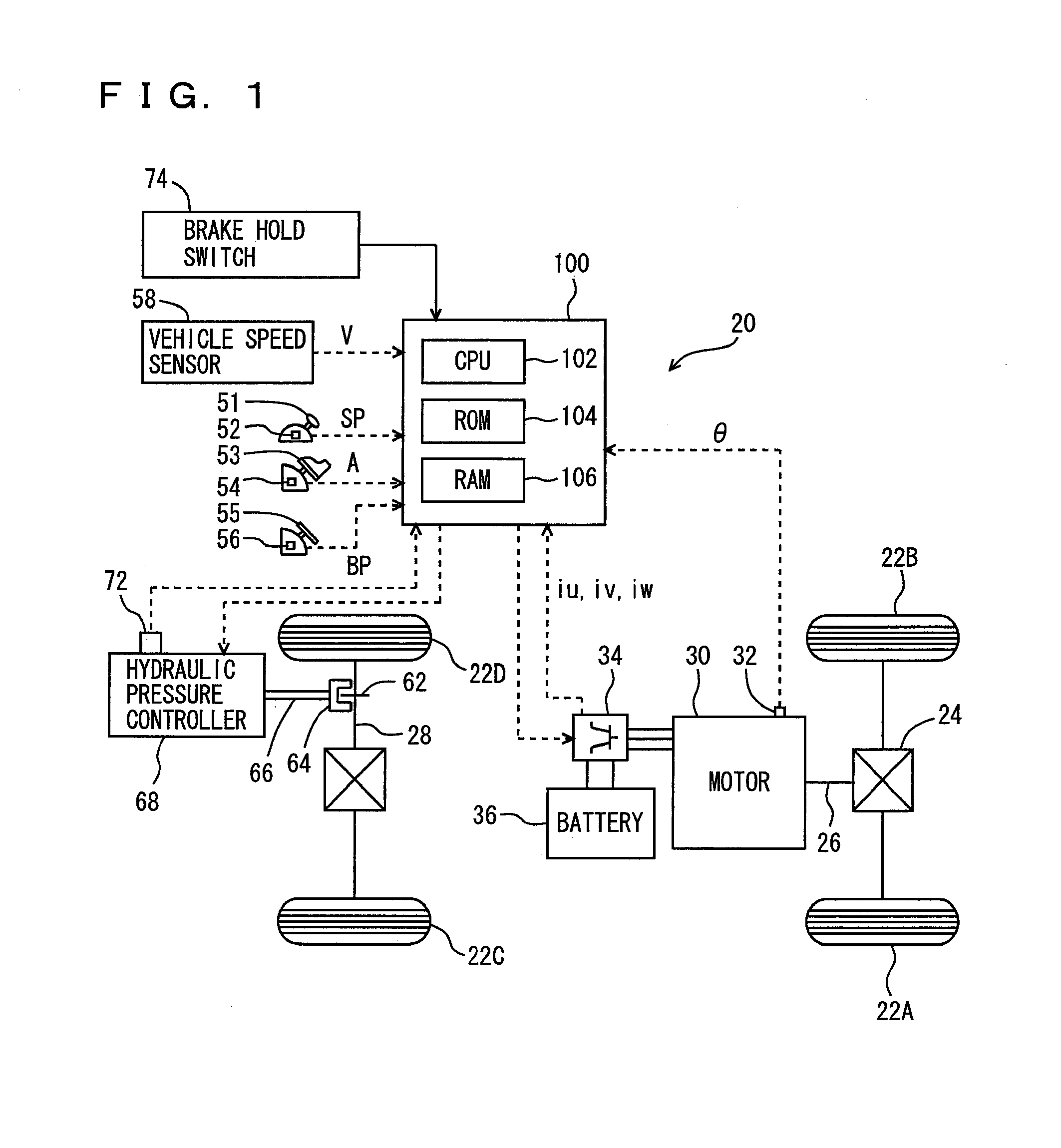
[0026]Referring to FIG. 1, a configuration of an electric vehicle 20 mounting the controller in accordance with the present invention will be described. The vehicle to which the controller of the present invention is applicable is not limited to the electric vehicle shown in FIG. 1, and it may be an electric vehicle of different type. Further, it may not be an electric vehicle but a hybrid vehicle that runs with power from an engine and from a motor.

[0027]Electric vehicle 20 includes wheels 22A, 22B, 22C and 22D, a propeller shaft 26 connected to wheels 22A and 22B via a differential gear 24, a motor 30 for traveling, outputting power for driving wheels to propeller shaft 26...


PUM


Abstract

An ECU releases brake hold control when an actual accelerator pedal position A exceeds a predetermined position A(0) while the brake hold control is being executed. Further, the ECU determines whether or not the actual accelerator pedal position A is larger than a position A(1), which is a value smaller than the predetermined position A(0), and if it is larger than the predetermined position A(1), executes a process for increasing a creep torque reflection ratio R to recover creep force that has been stopped.

Description

[0001]This nonprovisional application is based on Japanese Patent Application No. 2007-284239 filed with the Japan Patent Office on Oct. 31, 2007, the entire contents of which are hereby incorporated by reference.BACKGROUND OF THE INVENTION[0002]1. Field of the Invention[0003]The present invention relates to vehicle control and, more specifically, to control of a vehicle with a brake hold control function by which braking force is held even when a brake pedal is not stepped on by the driver.[0004]2. Description of the Background Art[0005]Recently, a vehicle has been proposed that has automatic transmission and executes control of holding braking force at a halt (brake hold control) even if a brake pedal is not operated, when degree of brake pedal operation (for example, amount of operation of the brake pedal) exceeds a prescribed degree while the vehicle is stopped in the forward position, in order to alleviate load of braking operation on the user, for example, in congestion. In th...

Claims


Application Information

Patent Timeline
Patent Type & Authority Patents(United States)
IPC IPC(8): G06F7/70B60K6/20G05D1/00
CPCB60T7/122B60T2201/06Y02T10/7258B60L15/2063B60L15/2081Y02T10/72Y02T10/64
Inventor UEOKA, KIYOSHIROOONISHI, KENJI
Owner TOYOTA JIDOSHA KK
Why Eureka
Try Eureka