SPM probe with shortened cantilever

a cantilever and probe technology, applied in the field of spm probes, can solve the problems of insufficient solutions proposed until now for a defined length of cantilever, low analysis speed, and limited scanning speed

Inactive Publication Date: 2011-08-30
NANOWORLD
View PDF9 Cites 4 Cited by
  • Summary
  • Abstract
  • Description
  • Claims
  • Application Information

AI Technical Summary

Benefits of technology

[0019]An aspect of the invention is to give the support element a special form wherein, compared with conventional probes, the lateral distance of the scanning tip to the longitudinal side edges of the nearest support element surface is significantly reduced and / or the distance between the cantilever top side carrying the scanning tip and the associated support element surface is significantly increased in comparison with the conventional probes.
[0020]The SPM probe according to the invention has an elongated support element with an essentially trapezoidal cross-section, with the cantilever placed at a front face side of the support element on a lateral edge, preferably the wide lateral edge. An essentially trapezoidal cross-section may also mean rectangular and / or stepped cross-sections. A plane extending between the scanning tip and a theoretical straight line passing through a critical corner associated with the lateral edge, parallel to the lateral longitudinal edges of the underside of the support element, forms an angle of tilt of at least 5 degrees relative to the transverse edge. ‘Critical corner’ means the corner that is closest to the sample during the scanning process. If, at the front transverse edge, two corners each are formed on both sides of the cantilever, for example in the form of a bevel, the critical corner is the one that has the shortest distance from the cantilever and would be the first to contact the surface of the sample. In addition, it would be reasonable to widen the support element from the front face side of the probe with the cantilever towards the opposite rear face side of the probe in order to improve the operability of the probe. As a consequence, the probe can be tilted up to 5 degrees laterally without the transverse edge of the support element facing the probe contacting the sample surface, thereby largely precluding damage to the probe.
[0022]The creation, on the support element, of the raised portion at whose narrower end the cantilever is fixed and whose height compensates for the possible lateral tilt of the probe reliably prevents the support element from contacting the sample surface, in particular in case of small, short cantilevers. By shifting the definition of the edge with the critical corner of the support element from the rear side of the support element to the front side of the support element where the cantilever is located, a simpler and, in particular, more reproducible manufacture becomes possible.
[0031]In one embodiment of the invention, the lateral flanks of the support element and the lateral flanks of the raised portion may be of identical inclination, and may follow each other in a stepped arrangement. In addition, preference is given to an embodiment of the invention where at least the face side flank to which the cantilever is attached has an undercut shape. Here, it is also an advantage if the lateral flanks of the longitudinal sides of the support element run towards each other preferably in the direction of the cantilever.

Problems solved by technology

A general and significant disadvantage of scanning probe microscopy is the low speed of the analysis because the probe scans the surface point by point.
Here, the scanning speed is limited by the scanning mechanism, on the one hand, but also by the resonant frequency of the cantilever of the probe.
While numerous approaches already exist for the reduction of thickness fluctuations, based on etch stop techniques with the help of additional intermediate layers in the base material (for example ‘silicon-on-insulator’ substrates, implanted intermediate layers, etc.), the solutions proposed until now for a defined length of the cantilever are insufficient.
The commonly used method of definition of the cantilever length by a lateral flank of the support element is very imprecise due to the large vertical distance between the starting plane of the etching process and the cantilever.
Fluctuations in the inclination of the etching flank and / or fluctuations of the thickness of the base material lead to significant variations of the cantilever length that are no longer acceptable for short cantilevers.
Even when cantilevers are mounted on a separately manufactured support element, by anodic bonding for example, the fluctuations of the mounting process are too large for the intended cantilever sizes so that the process cannot be used for very small cantilevers.
Although alternative known processes for a subsequent shaping of the cantilever by means of ablation with a focused ion beam will achieve the objective, they are costly individual-production steps.
Beside these difficulties regarding the manufacture of such SPM probes with cantilever and integrated scanning tip that are generally caused by the reduced dimensions, the problem of unintentional contact of the support element instead of the scanning tip becomes much greater with short cantilevers.
This would prevent the intended function and possibly even damage the sample to be examined.
The manufacture of the short edge of the support element as described above is subject to significant fluctuations in commonly used manufacturing processes such as wet-chemical anisotropic depth etching, with the consequence that this type of shaping cannot simply be applied to the case of smaller cantilevers and the significant size reduction of the support element edge that is necessary for these.
Alternative processes like the sawing of the lateral flanks of the support element soon reach their limits because they can only produce flanks that are oriented parallel to the direction of the cantilever.
However, due to their narrow width, support elements that are sawed sufficiently narrow with respect to tilting become impossible to manipulate.

Method used


Image

  • SPM probe with shortened cantilever
  • SPM probe with shortened cantilever
  • SPM probe with shortened cantilever

Examples


Embodiment Construction

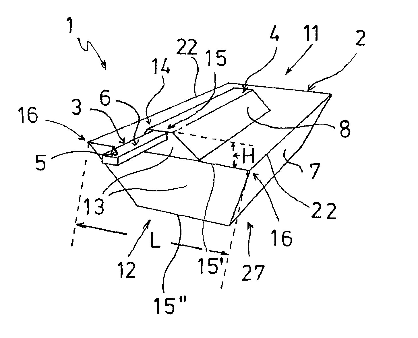
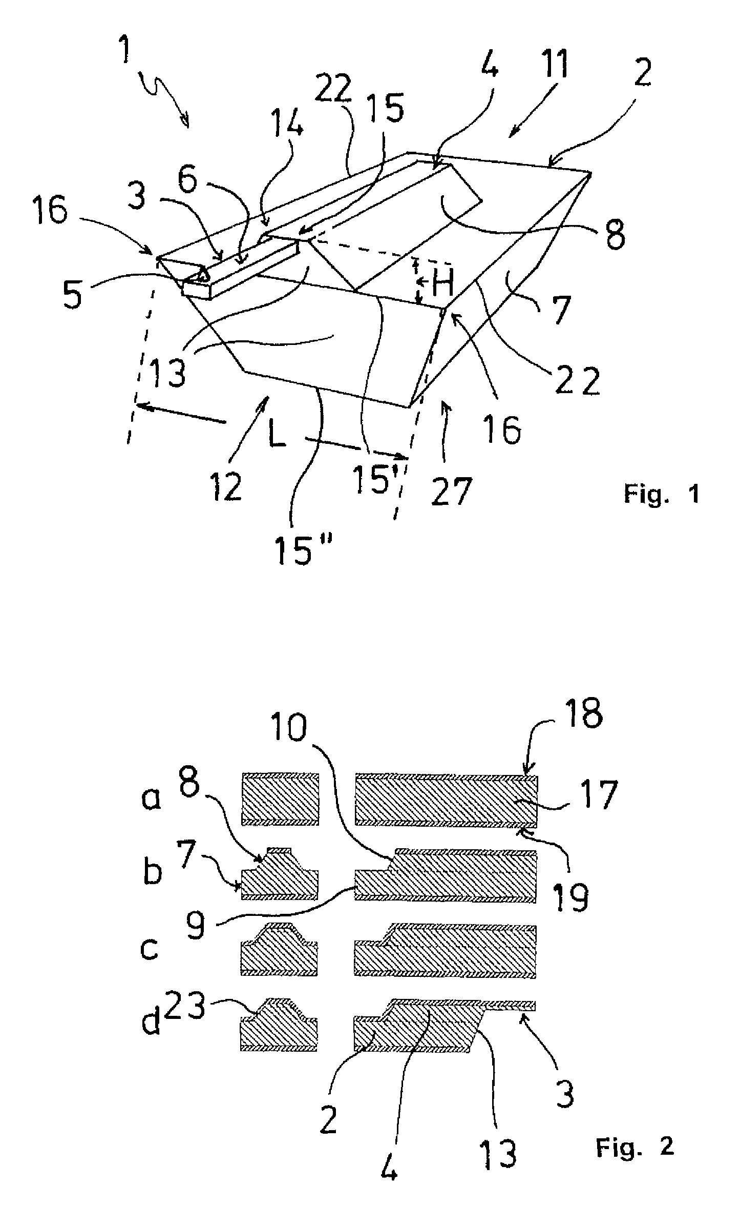
[0050]In the description of the embodiments, terms like top, bottom, top side, bottom side etc. refer to a common operating position of the SPM probe where the cantilever scans from above a sample located below it with a scanning tip pointed downward. In order to show details that would otherwise be obscured, the figures show the probe with a scanning tip pointing upward, contrary to the operating position.

[0051]FIG. 1 shows an SPM probe 1 with a support element 2 where the cantilever 3 starts from an elongated raised portion 4 that is carried by the support element 2. As is common, the cantilever 3 carries, remote from the support element 2, a scanning tip 5 on an underside 6 of the cantilever 3. Laterally, the support element 2 has longitudinal side flanks 7 and the raised portion 4 has longitudinal side flanks 8 as well as rear transverse side flanks 9, 10 that each connect two longitudinal side flanks 7 and 8, respectively. On the front face 12 above which the cantilever 3 protr...


PUM


Abstract

An SPM probe with an elongated support element and a cantilever projecting beyond the front face of the support element and carrying a scanning tip, with the cantilever arranged at a front face side of the support element of the probe, protruding there from a front face side flank, and with the support element having an essentially trapezoidal cross-section with a longer and a shorter transverse edge at the face side flank, and also with critical corners at one of the transverse edges of the face side flank that are closest to a sample during the scanning process, wherein the support element has an elongated raised portion extending in the longitudinal direction of the support element and of the cantilever, with the raised portion having an essentially trapezoidal cross-section, and with the cantilever arranged on the face side on a narrow transverse edge of the raised portion of the support element, and with the raised portion with the cantilever arranged preferably at the longer transverse edge of the face side flank of the support element, and with the plane extending between the scanning tip and a theoretical straight line passing through one of the critical corners, parallel to the lateral longitudinal edges of the underside of the support element, forming an angle of tilt of at least 5 degrees relative to the transverse edge.

Description

CROSS-REFERENCE TO RELATED APPLICATION[0001]The present application claims priority under 35 USC §119 to European Patent Application No. 08 005 248.3, filed on Mar. 20, 2008, the entire disclosure of which is incorporated herein by reference.TECHNICAL FIELD OF THE INVENTION[0002]The invention relates to an SPM probe with a support element and a cantilever that projects laterally from the support element and carries a scanning tip at its free end, and a process for manufacturing such probes.DESCRIPTION OF THE RELATED ART[0003]Scanning probe microscopes are generally known and are used for high-resolution scanning of the surface of samples by means of sensitive sensors, so-called SPM probes. In all these microscopes, probes are used whose sensor is formed by a spring-action micro-cantilever that has at one end a support element for attachment to a probe carrier and at the other end a sensor tip for scanning the sample.[0004]Scanning probe microscopy has become an established technique...

Claims


Application Information

Patent Timeline
Patent Type & Authority Patents(United States)
IPC IPC(8): G01Q70/02G01Q60/38
CPCB82Y35/00G01Q70/16G01Q70/10
Inventor SULZBACH, THOMASRICHTER, CHRISTOPH
Owner NANOWORLD
Why Eureka
Try Eureka