Wet oil sump for four cycle engine

a technology for oil sump systems and engines, applied in the direction of pressure lubrication, lubrication indication devices, lubrication elements, etc., can solve the problems of extra horsepower required to drive the drive gear through the oil sump, the system is more complex, and the drive gear is within the oil sump

Active Publication Date: 2011-09-06
POLARIS IND INC
View PDF18 Cites 28 Cited by
  • Summary
  • Abstract
  • Description
  • Claims
  • Application Information

AI Technical Summary

Benefits of technology

[0008]In yet another embodiment, an oil pump assembly comprises an oil pump body and an oil pump case for insertion within a crankcase; an oil sump member for extending into an oil reservoir; a pumping member receivable in the pump case, and being profiled to pump oil upon pumping movement thereof. A drive gear drives the pumping member and a drive gear shield at least partially surrounds the drive gear and prevents the drive gear from being submersed into oil in the oil reservoir.

Problems solved by technology

As a dry sump system utilizes a closed volume for housing the lubricating oil, the volume of oil required to supply the system is less however the system is more complex as it requires an extra reservoir.
The dry sump system however is less sensitive to the angles at which it operates and is therefore sometimes desired for extreme angles.
This location of the drive gear within the oil sump may produce disadvantages to the overall system for a number of reasons.
First, extra horsepower is required to drive the drive gear through the oil sump due to the resistance of the gear traveling in the oil.
Second, the gear driven within the oil aerates the oil which in turn causes a decrease in the lubrication effect of the oil due to the air within the oil.
Thirdly, driving the drive gear through the oil heats the oil which then in turn places a larger load on the oil cooler which may also cause an overall reduction in horse power.

Method used


Image

  • Wet oil sump for four cycle engine
  • Wet oil sump for four cycle engine
  • Wet oil sump for four cycle engine

Examples


Embodiment Construction

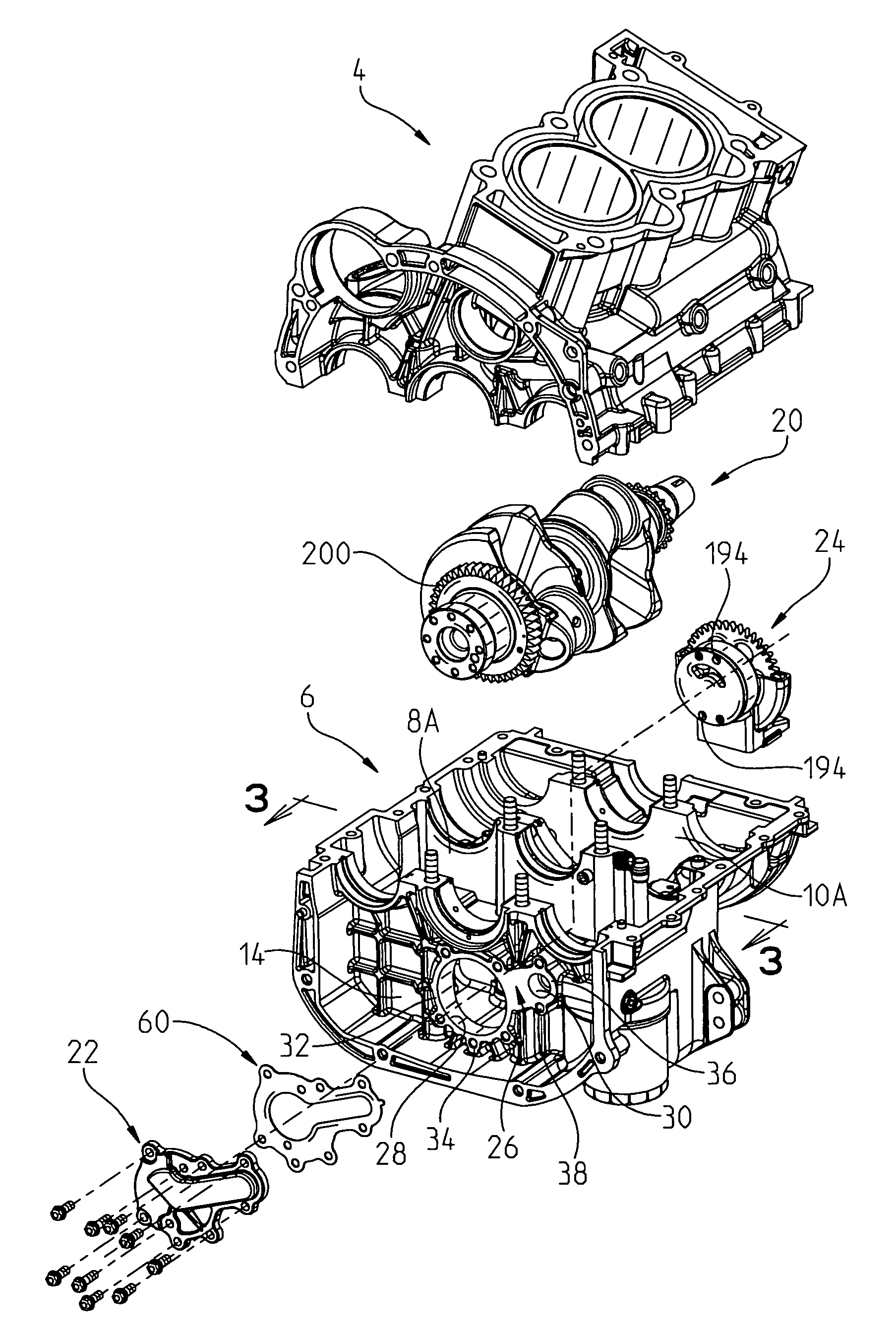
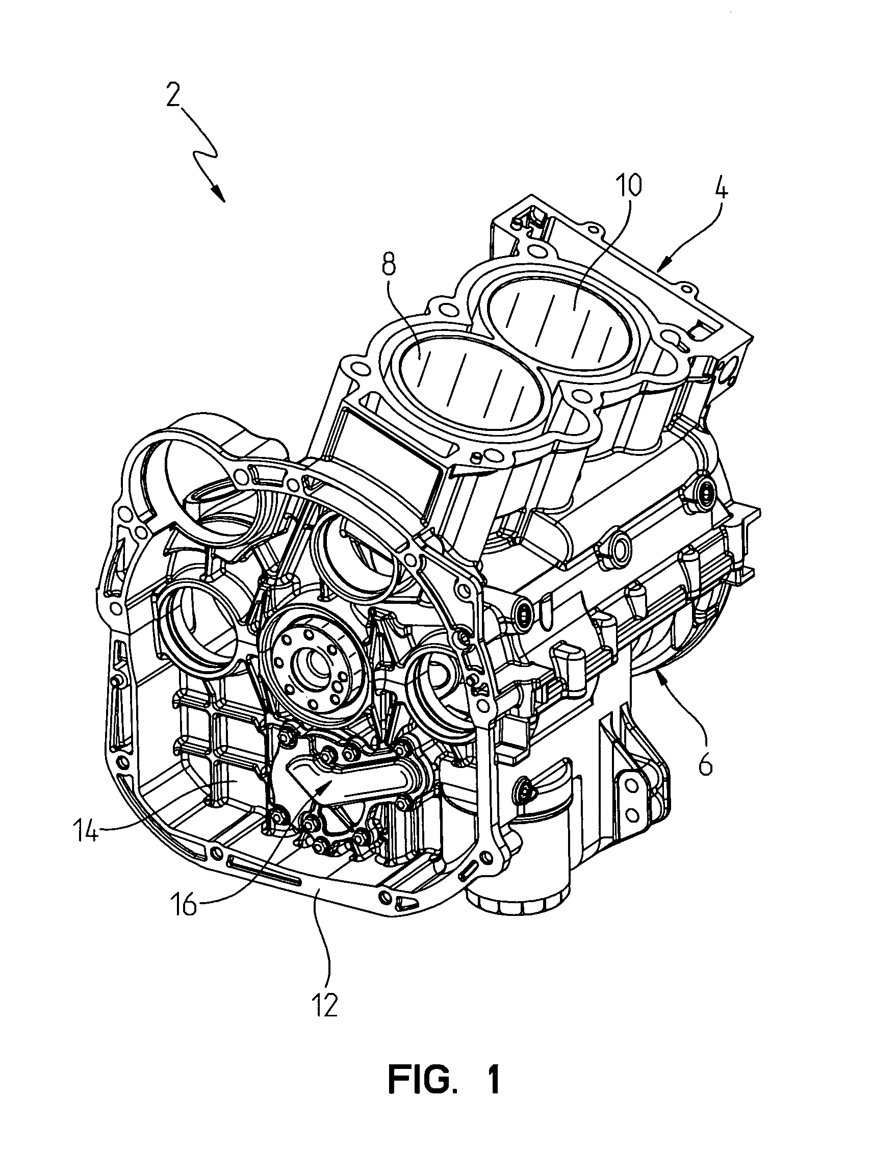
[0025]With reference first to FIGS. 1 and 2, a four cycle in-line two cylinder engine is shown at 2 comprised of an engine head 4 and an engine crankcase at 6. Engine head 4 includes first and second cylinders 8, 10 (and crankcase compartments, 8A, 10A (FIG. 2)), and a bell housing 12 defined by a combination of head 4 and crankcase 6. Crankcase 6 includes a rear wall 14 to which an oil pump assembly 16 is attached as described further herein. Engine head 4 and crankcase 6 may be comprised of a hypereutectic aluminum alloy material (similar to that disclosed in U.S. Pat. No. 5,253,625, which is incorporated herein by reference) however where the cylinder bores are honed and polished to a point where the silicon is proud of the remaining surface material in the bore.

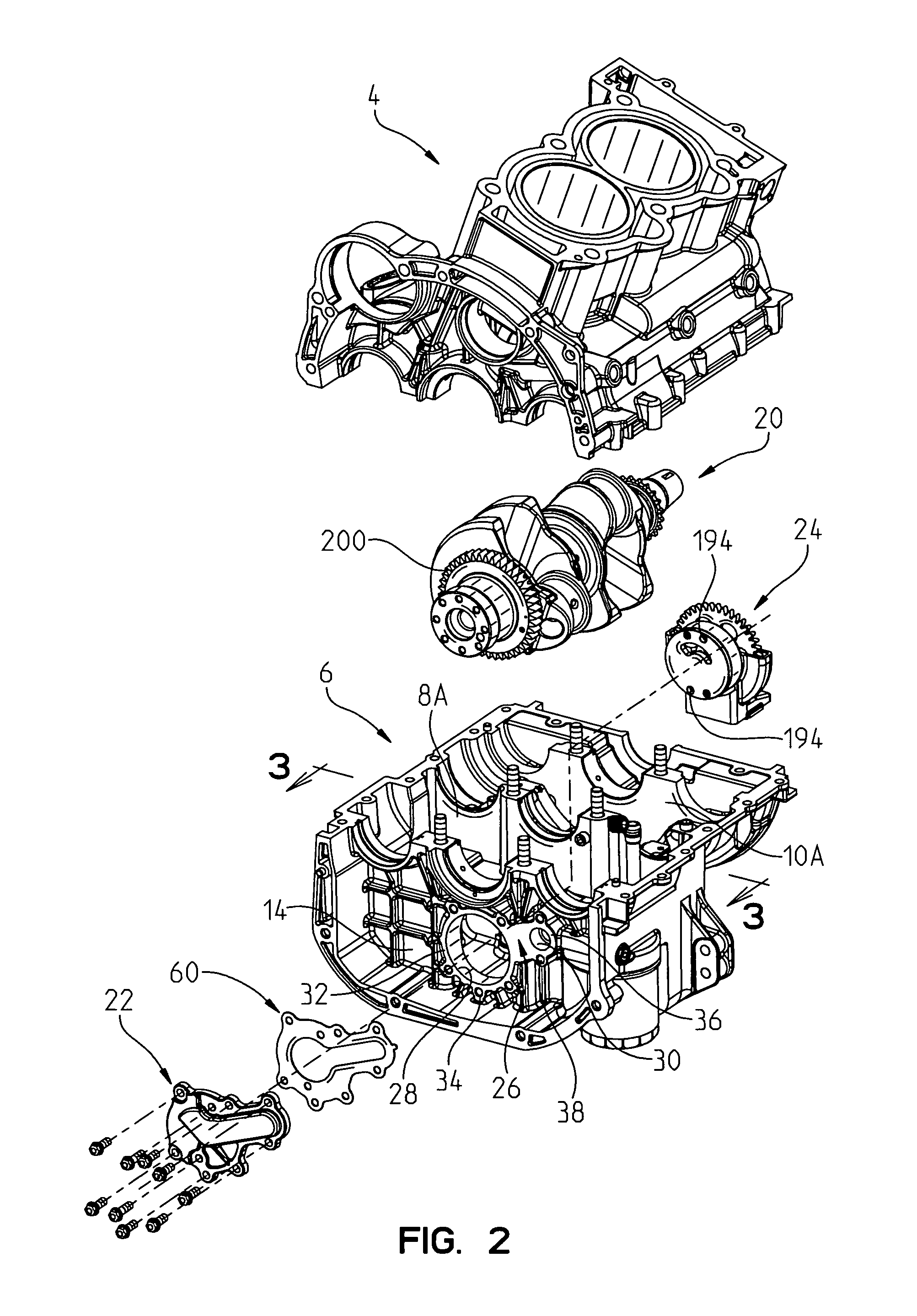
[0026]With reference now to FIGS. 2 and 2A, head 4 is shown exploded away from crankcase 6, with crankshaft 20 also shown removed. Oil pump assembly 16 is also shown exploded away from the crankcase and includes an outer ...


PUM


Abstract

An oil pump assembly is shown for wet oil sump applications at extreme angles for power sports equipment. The oil pump is comprised of a pump body, an oil pick-up and a driven gear shield, where these components may be integrally formed from die cast aluminum. The pump body includes a rotor body housing a gerotor assembly for pumping. The oil pump is attached to the rear wall of the crankcase and below the crankshaft, and is driven by the crankshaft.

Description

FIELD OF INVENTION[0001]The subject invention relates to a wet oil sump system for four cycle engines, with particular use in power sports vehicular applications.BACKGROUND OF THE INVENTION[0002]Lubrication systems in four cycle engines typically take one of two approaches, the first, a “wet oil sump” has a pool of oil at the bottom of the crankcase or oil pan together with an oil sump that siphons oil from the sump; or second, a “dry sump” which has an extra oil tank provided outside of the engine with an internal pump to distribute the oil to the engine. In either system, oil is distributed to lubricate such items as the main bearings of the crankshaft, the pistons and cylinder walls, connecting rods, cam shaft bearings, valves, and the like. In either the “wet sump” or “dry sump” system, oil is distributed through the various points and returned to the sump in a relatively closed loop system.[0003]In the power sports industry, for example in four cycle engines that power snowmobi...

Claims


Application Information

Patent Timeline
Patent Type & Authority Patents(United States)
IPC IPC(8): F01M11/10
CPCF01M1/02F01M11/0004F01M2001/0238F01M2001/0269F01M2001/0284F01M2011/007F01M2011/0079
Inventor BLUHM, MICHAEL JOHN
Owner POLARIS IND INC
Why Eureka
Try Eureka