Dialysis device

a technology of dialysis device and membrane, which is applied in the direction of membrane, multi-stage water/sewage treatment, separation process, etc., can solve the problems of affecting the recovery of samples, so as to improve the recovery of samples

Active Publication Date: 2011-09-06
ALAM AFTAB
View PDF7 Cites 4 Cited by
  • Summary
  • Abstract
  • Description
  • Claims
  • Application Information

AI Technical Summary

Benefits of technology

[0025]Preferably, the inner and outer elements are made of differentially flexible materials, wherein the inner element is more rigid than the outer element. Preferably, as an example the inner element is made of polypropylene, polycarbonate, nylon or similar rigid materials where as the outer element is made of polyethylene (high or low density) or ethylene. The greater flexibility of the outer elements allows flexing or expansion of the outer element at the time of assembly allowing interlocking of the two elements.
[0026]For assembly of the two elements into a dialysis reservoir, a dialysis membrane of a diameter larger than the diameter of the leading end of the inner element is placed between the outer and inner element and the inner element is pushed into the outer element until the two elements irreversibly interlock. After assembly of the two elements, a gasket is externally placed on the dialysis membrane through the open end of the inner element, the gasket is supported on the flange of the outer element. The diameter or circumference of the gasket is equal to or less than the inner diameter of the inner element. The dialysis reservoir is mounted on the open end of the dialysis tube. When the dialysis reservoir is fasten on the dialysis tube the open end of the dialysis tube press against the externally placed gasket support from the opposite side by the flange on the outer element thus creating tight seal between the dialysis reservoir, membrane, and the dialysis tube.
[0027]For dialysis of a liquid sample, sample is placed in the dialysis tube and the dialysis reservoir is mounted on the open end of the dialysis tube. When the dialysis reservoir is fastened (mounted) on the open end of the dialysis tube the open end of the dialysis tube compresses (press) against the externally placed gasket inside the dialysis reservoir thus creating a liquid tight seal for the sample inside the dialysis tube. The assembled dialysis device is secured on a floating device in inverted position allowing the sample in the dialysis tube to rest on the dialysis membrane in the dialysis reservoir. The assembly of dialysis device and the floating device is floated in a dialysis liquid buffer tank for dialysis and exchange of molecules across the dialysis membrane. After dialysis process is complete the liquid sample inside the tube is collected by removing the dialysis reservoir from the dialysis tube. The dialysis device may be briefly centrifuged (before undoing or removing the dialysis reservoir) allowing the sample to collect at the bottom of the dialysis tube improving recovery of the sample.

Problems solved by technology

Dialysis membranes are fragile and cannot withstand mechanical stress without damage or altering of the porosity of the dialysis membrane.
Any glue applied on the membrane will also undermine porosity of the membrane.
Furthermore, wide verities of dialysis membrane are manufactures and provided for use and storage in aqueous medium making it even more difficult to glue on any surface.
The U.S. Pat. No. 6,217,772 fails to adequately describe the self-locking structure to lock the outer and inner elements relative to one another.
If membrane wraps over the inner member the disclosure does not teach how to avoid the membrane interfering with the self locking mechanism.
The above identified patent specification lacks of specificity makes it difficult for those skilled in the art to reproduce this embodiment of the invention without further innovation and engineering challenge.

Method used


Image

  • Dialysis device
  • Dialysis device
  • Dialysis device

Examples


Embodiment Construction

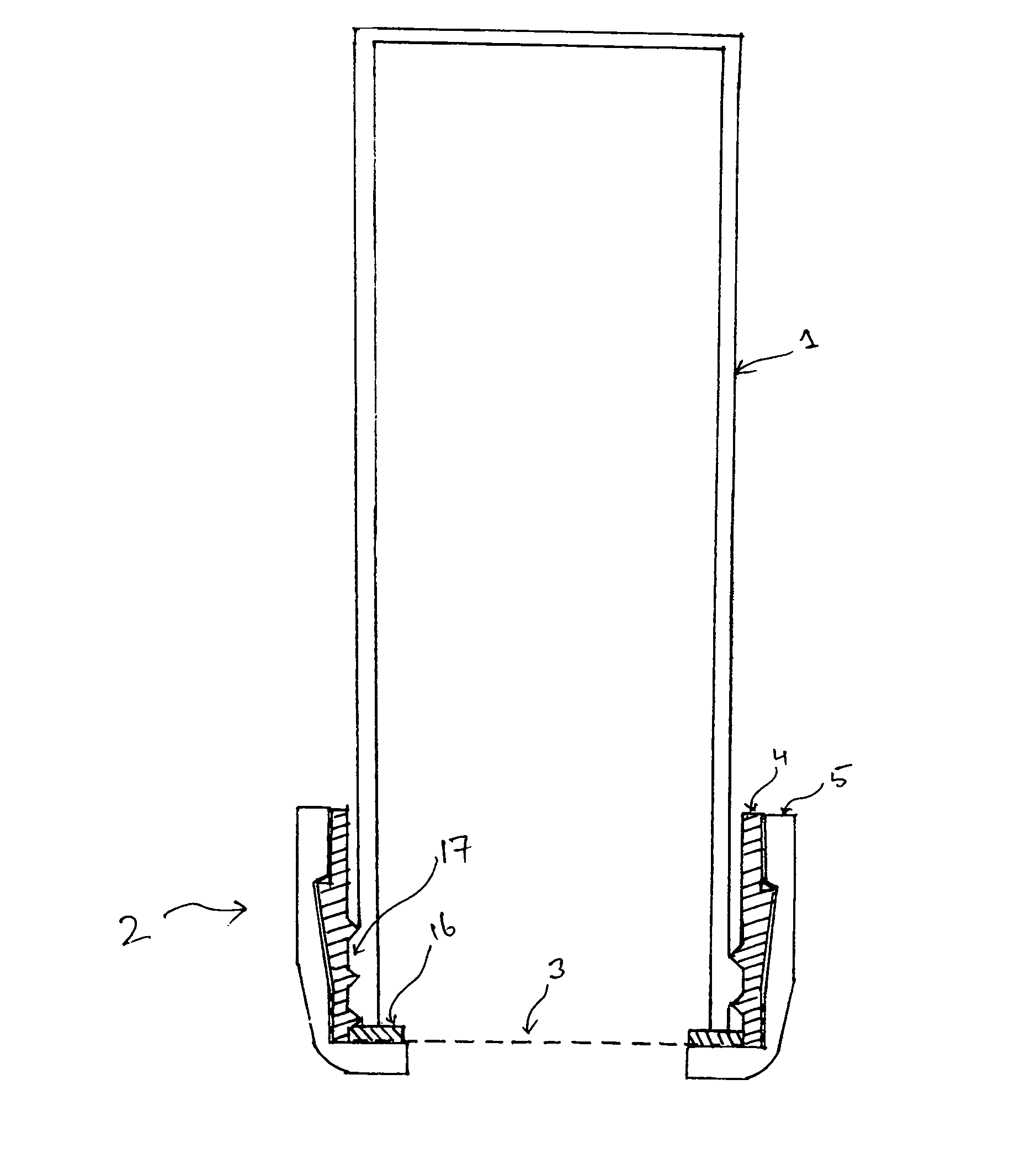
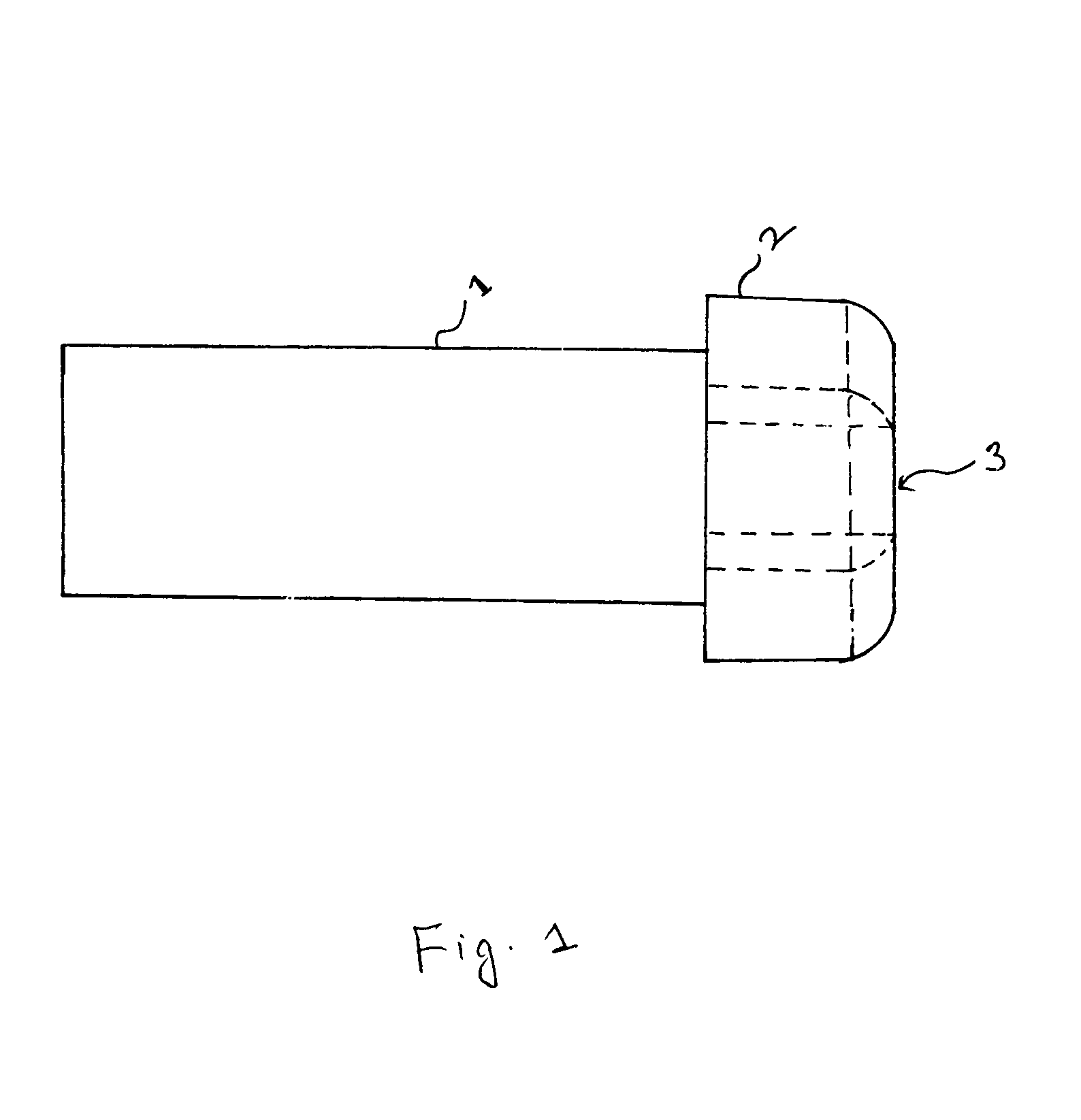
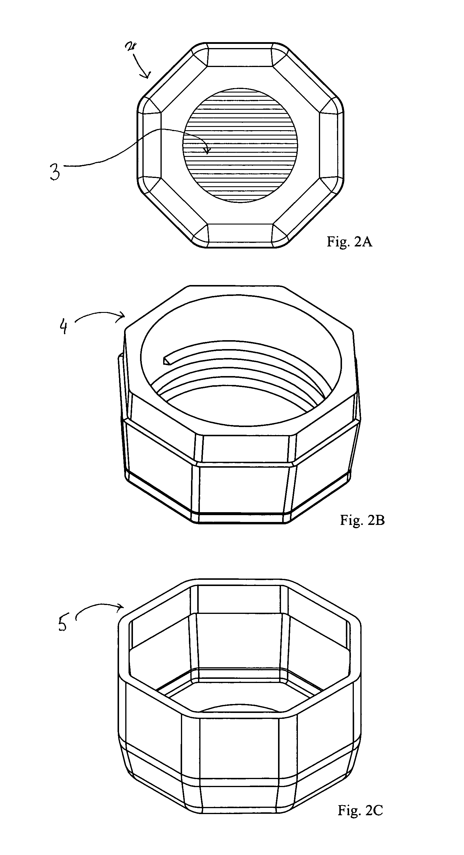
[0042]The embodiment of the present invention shown in FIG. 1 contains a dialysis tube 1 and a cap 2, wherein the cap acts as a dialysis reservoir. The dialysis tube 1 has an open end and the end opposite the open end is closed. The outer surface of the open end of the dialysis tube is provided with mounting threads 17 (FIG. 8). The dialysis reservoir 2 is provided with multifaceted geometric structure, preferably containing eight faces; FIG. 2A shows front view of the dialysis reservoir with eight faces. The dialysis reservoir has an open end which is mounted on the open end of the dialysis tube 1 and the end opposite the open end is provided with a dialysis membrane 3, as shown in FIG. 2A.

[0043]The dialysis reservoir 2 is made of an inner element 4 shown in FIG. 2B and FIG. 3A and an outer element 5 shown in FIG. 2C and FIG. 4A. The inner element is designed to sleeve into the outer element as shown in FIG. 7 in fully assembled position. Preferably, the outer element is made of po...


PUM

PropertyMeasurementUnit
tapering angleaaaaaaaaaa
interlocking angleaaaaaaaaaa
tapering angleaaaaaaaaaa

Abstract

A dialysis device having a dialysis tube with a closed end and an open end, the open end is provided with a dialysis reservoir having a dialysis membrane.

Description

CROSS REFERENCE TO RELATED APPLICATIONS[0001]This application claims priority from the provisional patent application No. 61 / 199,072, filing date Nov. 14, 2008.HISTORY OF THE INVENTION[0002]Dialysis of samples for exchange of buffers & equilibration is widely used in chemical and biochemical processes.[0003]The U.S. Pat. No. 6,217,772 describes a dialysis device in centrifuge tube configuration wherein the cap of the tube, described in the invention as dialysis reservoir is provided with a dialysis membrane for exchange of buffer across the dialysis membrane. The cap on the dialysis tube is screw thread mounted on the dialysis tube and the whole assembly can be inverted in to a dialysis tank for dialysis. One of the embodiments of the invention describes the cap or the dialysis reservoir made of an outer element and an inner element. The outer and inner elements are designed to sleeve over or telescopically receive the inner element and the two pieces fit tightly or snugly together....

Claims


Application Information

Patent Timeline
Patent Type & Authority Patents(United States)
IPC IPC(8): B01D61/24B01D61/28
CPCB01D61/243B01D61/28B01D63/087Y10T436/25375B01D2313/04Y10T436/255
Inventor ALAM, AFTAB
Owner ALAM AFTAB
Why Eureka
Try Eureka