
Shielding device

a shielding device and shielding technology, applied in the direction of antenna details, cross-talk/noise/interference reduction, antennas, etc., can solve the problems of adversely affecting the signal integrity of synthesizers within the same frequency channel, and the complexity of modern wireless communication apparatuses such as cellular phones or gps tracking systems as technology develops

Active Publication Date: 2011-09-06
XUESHAN TECH INC
View PDF6 Cites 42 Cited by
  • Summary
  • Abstract
  • Description
  • Claims
  • Application Information

AI Technical Summary

Benefits of technology

"The invention provides an improved shielding device that can prevent the pulling effect of electromagnetic waves. It also reduces the number of shielding cases needed, saving manufacturing costs. The shielding device has a shield body with a top piece and sidewall pieces, and an electromagnetic band-gap (EBG) structure on the top piece. The EBG structure has a periodic pattern that prevents the propagation of electromagnetic waves within a range of frequencies. The invention also includes a printed circuit board with shielding protection, where the shielding device covers the electronic components on the board."

Problems solved by technology

Modern day wireless communication apparatuses such as cellular phones or GPS tracking systems are becoming more and more complex as technology develops.
It is believed that the PA pulling effect is caused by the higher-order harmonics power originated from the RF power amplifier, which adversely affects the signal integrity of synthesizer within the same frequency channel.

Method used


Image

  • Shielding device
  • Shielding device
  • Shielding device

Examples


Embodiment Construction

[0017]The shielding device according to this invention may be applied to various wireless communication apparatuses including but not limited to Global Positioning System (GPS) and handheld communication devices such as cellular phones. Without the intention of a limitation, the invention will now be described and illustrated with the reference to several embodiments.

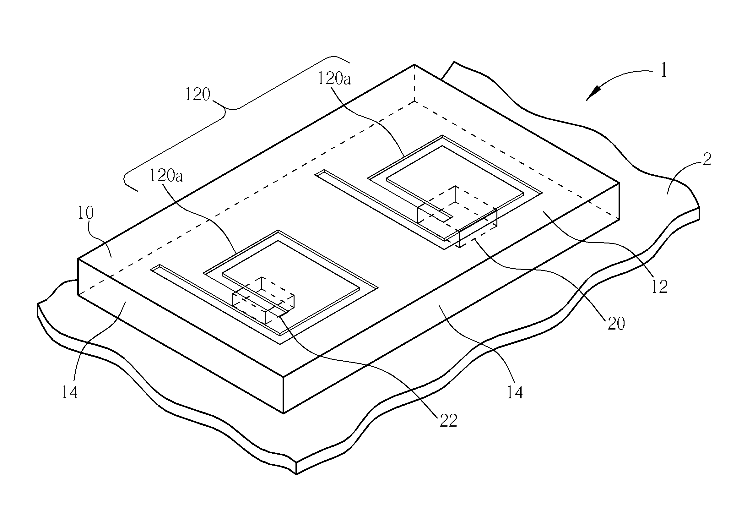
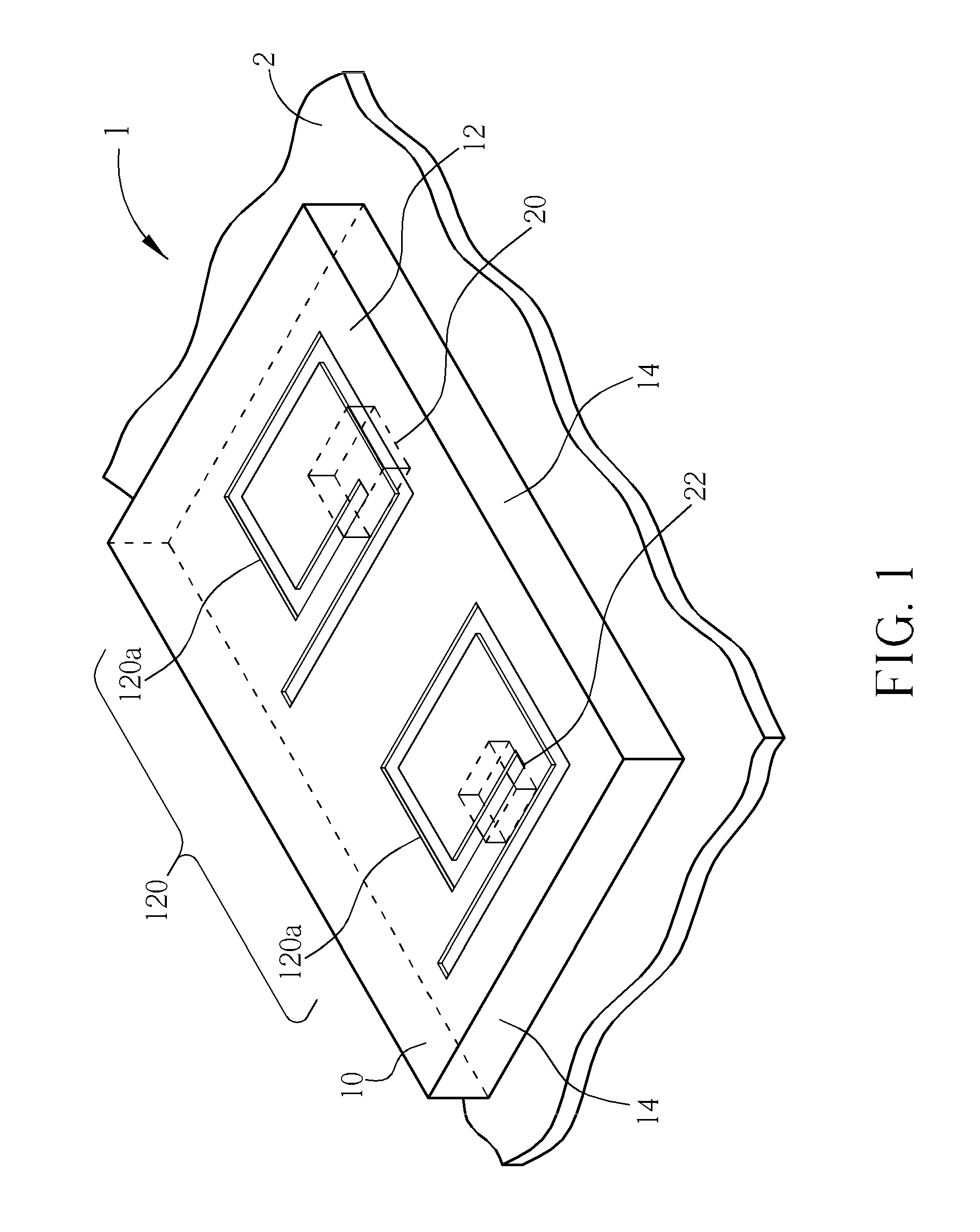
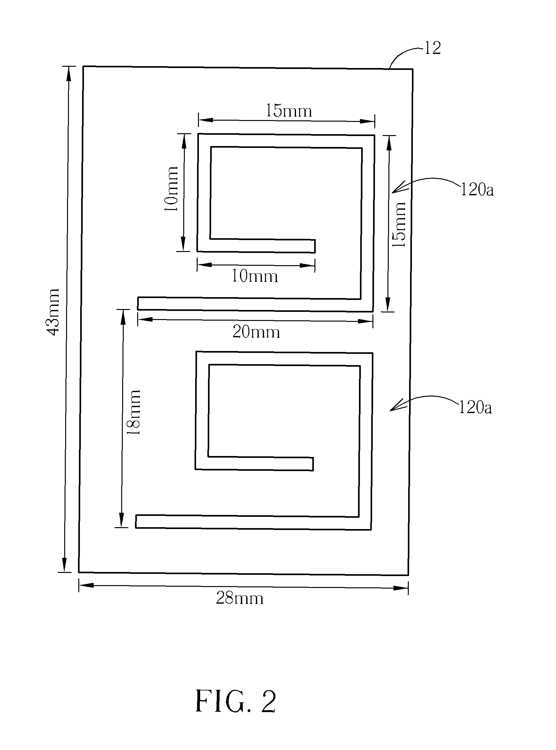
[0018]FIG. 1 is a schematic, perspective diagram illustrating a shielding device in accordance with one embodiment of the invention. The shielding device 1 includes a monolithic shield body 10 having a top piece 12 and four sidewall pieces 14. In this embodiment, the top piece 12 and sidewall pieces 14 are in the form of plates. The shield body 10 is a downwardly opened, box-like structure. The top piece 12 and the sidewall pieces 14 define a single covering space (or single compartment) 101 for shielding at least two radio frequency (RF) electronic components 20 and 22 that are mounted on a printed circuit board (PCB) ...


PUM


Abstract

A shielding device for serving as an electromagnetic shield includes a shield body having a top piece and a plurality of sidewall pieces, and an electromagnetic band-gap (EBG) structure disposed on the top piece of the shield body.

Description

BACKGROUND OF THE INVENTION[0001]1. Field of the Invention[0002]The present invention relates generally to a shielding device served to shield electronic components in wireless communication apparatuses and, more particularly, to a shielding case that is capable of mitigating interference between the electronic components that are shielded by the same shielding case.[0003]2. Description of the Prior Art[0004]Modern day wireless communication apparatuses such as cellular phones or GPS tracking systems are becoming more and more complex as technology develops. Consumers demand smaller devices that still maintain good reception, high overall performance and large frequency range. Component placement is crucially important at RF frequencies, as interference from various components can hinder or block reception of signals. To avoid as much as possible any unwanted influence of electromagnetic radiation from devices such as RF power amplifiers or baseband chips, it is known to shield such...

Claims


Application Information

Patent Timeline
Patent Type & Authority Patents(United States)
IPC IPC(8): H05K9/00
CPCH01Q1/526H05K1/0236H05K9/0026
Inventor WU, WEN-CHOU
Owner XUESHAN TECH INC
Learn More