Electrical power tool

a power tool and power technology, applied in the field of electric power tools, can solve the problems of insufficient illumination of the display window, inability to provide sufficient illumination of the power tool, and difficulty in arranging the optical fiber in the main housing, etc., and achieve the effect of saving power consumption, small size, and sufficient brightness

Inactive Publication Date: 2011-09-13
KOKI HLDG CO LTD
View PDF14 Cites 44 Cited by
  • Summary
  • Abstract
  • Description
  • Claims
  • Application Information

AI Technical Summary

Benefits of technology

[0008]In view of the foregoing, it is an object of the present invention to provide an electrical power tool that is capable of illuminating a wide range including a work area and capable of preventing shadows from being generated, thereby improving workability at dark places.
[0017]Preferably, the outer circumferential surface includes a display portion and a transparent portion. The numbers are displayed on the display portion. The display portion is non-transparent. The transparent portion is capable of transmitting light. With this arrangement, since the numbers indicative of torque setting values are displayed on the non-transparent display portion and sufficient brightness is provided by the transparent portion, the numbers can be seen clearly even at dark places and thus torque adjustments can be achieved easily and accurately.

Problems solved by technology

However, the conventional electrical power tool disclosed in Japanese Patent Application Publication No. 2003-211374 illuminates only the work area in a spotlighting manner.
Thus, the power tool cannot illuminate a wide range including the work area, and also tends to generate shadows that can prevent efficient work.
Hence, sufficient illumination may not necessarily be provided to the display window.
In addition, arrangement of the optical fiber in the main housing is not easy.

Method used


Image

  • Electrical power tool
  • Electrical power tool
  • Electrical power tool

Examples


first embodiment

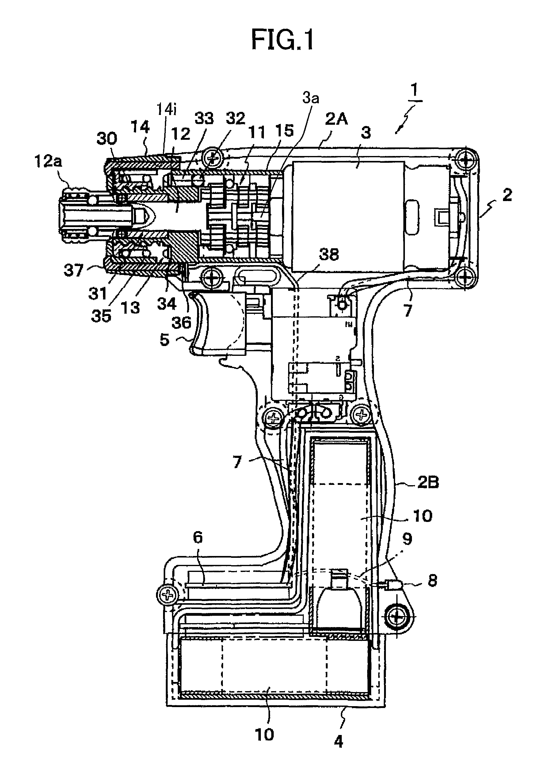
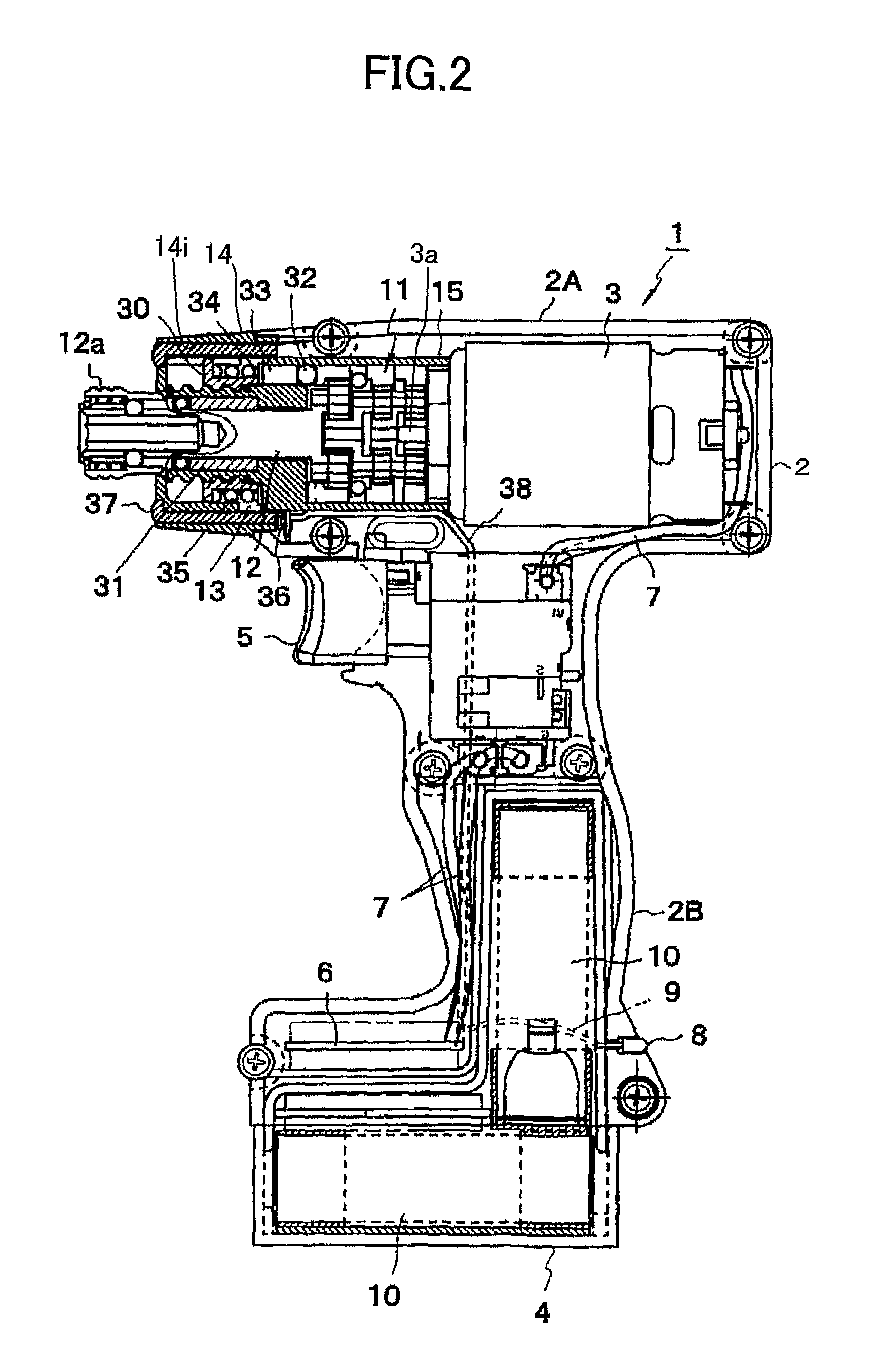
[0067]The driver drill 1 of the first embodiment includes a housing 2 formed of resin and having substantially a T-shape in a side view. The housing 2 includes a main body section 2A extending in the front-rear direction, and a handle section 2B extending downward from the main body section 2A and formed as an integral part with the main body section 2A. A lower part of the handle section 2B is formed with a space for accommodating a control board 6 described later.

[0068]An electrical motor 3 generating a driving force and having an output shaft 3a is accommodated in the main body section 2A such that the output shaft 3a extends in the front-rear direction. A battery 4 is detachably mounted to a lower end of the handle section 2B. The battery 4 includes three lithium ion batteries 10 therein. A switch 5 is provided at an upper end of the handle section 2B. The switch 5 is for turning ON and OFF the power supplied from the battery 4 to the electrical motor 3 for starting and stopping...

second embodiment

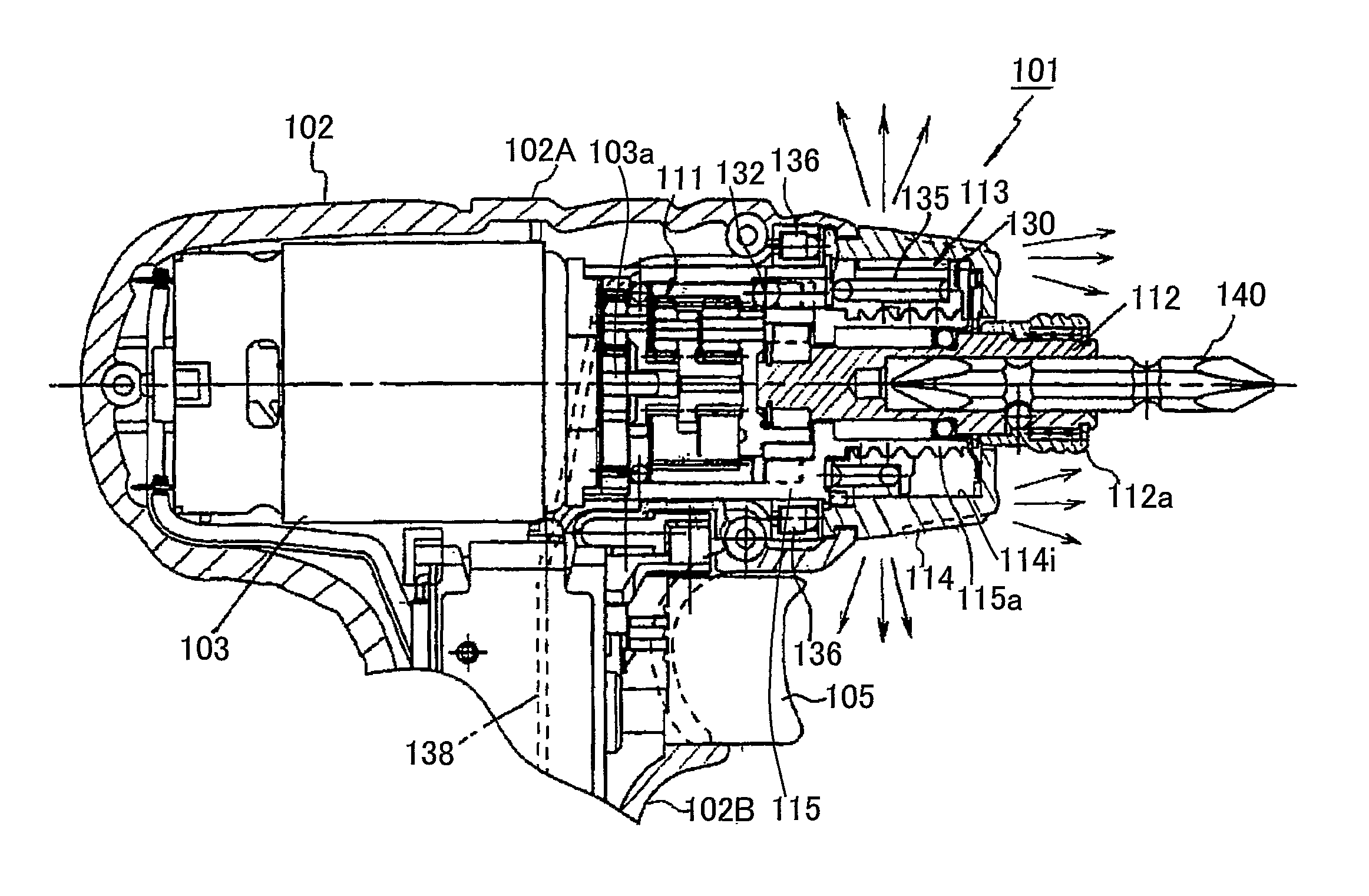
[0091]As shown in FIG. 7, the driver drill 101 of the second embodiment includes two LEDs 136 that are arranged at a front end portion of the main body section 102A, the front end portion being coupled with a rear end of the torque adjusting dial 114. Here, one of the two LEDs 136 is arranged at a top portion of the front end portion, while the other one of the two LEDs 136 is arranged at a bottom portion of the front end portion. The two LEDs 136 are electrically connected with the battery (not shown) via a lead wire 138 and the switch 105. Reflection plates (not shown) are provided at rear sides of respective ones of the two LEDs 136. B0023,0009

[0092]The torque adjusting dial 114 will be described in greater detail while referring to FIG. 8. FIG. 8 is a development view showing the torque adjustment dial 114, drawn by developing views from directions perpendicular to the driver bit 140 around the torque adjusting dial 114. The upper side of FIG. 8 corresponds to the front side of ...


PUM

PropertyMeasurementUnit
rotational driving forceaaaaaaaaaa
torqueaaaaaaaaaa
transparentaaaaaaaaaa

Abstract

An electrical power tool includes a housing, an electrical motor, an end-bit holding section, a transmitting mechanism, a cap, and a lighting section. The housing has one end. The electrical motor is accommodated in the housing and is configured to generate a rotational driving force. The end-bit holding section is provided at the one end and is rotatable about a rotational axis. The transmitting mechanism transmits the rotational driving force to the end-bit holding section. The cap is attached to the one end. The lighting section allows an entirety of the cap to be luminous.

Description

TECHNICAL FIELD[0001]The present invention relates to an electrical power tool and more specifically, to an electrical power tool having light for illuminating a work area.BACKGROUND ART[0002]A hand-held type electrical power tool such as a driver drill is conventionally known. Such a power tool includes a housing accommodating an electrical motor that generates a rotational driving force. The rotational driving force is transmitted to an end-bit holding section to rotate the end-bit holding section and an end bit such as a driver bit mounted on the end-bit holding section, thereby performing a desired work such as screw driving.[0003]When performing the desired work using such a power tool in dark places such as attic and under-floor spaces where natural light does not reach, it is difficult to accurately perform the desired work such as screw driving due to darkness.[0004]Japanese Patent Application Publication No. 2003-211374 discloses an electrical power tool including a light a...

Claims


Application Information

Patent Timeline
Patent Type & Authority Patents(United States)
IPC IPC(8): B25B23/18
CPCB25B21/00B25B23/18B25F5/021
Inventor UEDA, TAKASHIARADACHI, TAKAOTOUKAIRIN, JUNICHI
Owner KOKI HLDG CO LTD
Why Eureka
Try Eureka