
Remote-phosphor LED downlight

a technology of led downlights and led downlights, which is applied in the direction of semiconductor devices for light sources, fixed installations, lighting and heating apparatus, etc., can solve the problems of difficult lighting applications, low efficiency, and low luminance of downlights, and achieves low heat energy concentration, low luminance, and elimination or substantially reducing any glare factor

Active Publication Date: 2011-09-13
SEOUL SEMICONDUCTOR
View PDF9 Cites 80 Cited by
  • Summary
  • Abstract
  • Description
  • Claims
  • Application Information

AI Technical Summary

Benefits of technology

The aforementioned thermal limitation of LEDs is overcome in the present application by separating the blue LED and the yellow phosphor in white LEDs. Then the heat-producing LEDs can be situated at the front (bottom) of the downlight, facing backwards (upwards, into the can), so that only the remote phosphor need be at the back (top). This allows the LEDs to have a heat sink that is located at the open (bottom end) face of the can or, if needed, just outside the can. It also allows for an active cooling device to be attached to the can instead of, or in addition to, a passive heatsink. An example of a commercially available active cooling device suitable for this purpose is the Nuventix Synjet cooler, which can easily handle 15 to 20 Watts.
For a preferred embodiment, directly substituting for a typical 2 to 5 inch (50 to 125 mm) diameter downlight producing a beam of 30-40° half angle, the remote phosphor patch will be much larger (typically an inch or two, 25 to 50 mm, across) than the LED source, (typically a chip 1 mm across or a small array of such chips). Thus, the heat load of the remote phosphor is typically not a problem, because the large area of the phosphor results in a low concentration of heat energy to be dissipated. There is typically a secondary optic on the blue LED, so that all its light will shine only on the remote phosphor at the back (top) of the downlight. The most practical secondary optic is a cone-sphere combination, because a conical reflector can use high-reflectivity films manufactured flat. The conical reflector is oriented with its open smaller end downwards, with the LED light source simply placed within the small lower opening of the cone so that all the light emission from the LED is captured by the cone and reflected upwards.
In the cone-sphere embodiment, a plano-convex lens entirely covers the cone's large upper opening and sends all the LED's blue light to the remote phosphor or near enough to it that a primary reflector on the inside of the can will redirect onto the phosphor any rays that do not reach the phosphor directly. The relatively large remote phosphor that the blue LED excites will have relatively low luminance as compared to much smaller conventional white LEDs, eliminating or substantially reducing any glare factor. The heat sink for the blue LEDs can be located down low, exposed to the ambient air below the visible ceiling, enabling adequate cooling even for a 10-20 Watt blue LED package. Such power levels are too much to be easily accommodated in an installation in the top of a sealed hot can, closed to outside air, even with a fan. With the current proposal, only the phosphor heats the interior of the can, so the interior of the can becomes less hot than if the LEDs were in the top of the can. In addition, only the phosphor is in the top of the can, and the phosphor is far less vulnerable to heat damage than the LEDs themselves.

Problems solved by technology

Even in the rare cases when heat is transmitted through the can to a heat sink or heat exchanger on the outside of the can, the heat exchanger is typically in stagnant air within a false ceiling, and is not very effective.
LEDs, however, are sensitive to excessive temperatures and thus find downlights to be a more difficult lighting application than anticipated.
This is because their heat cannot safely be dissipated passively into the stagnant hot air of the typical downlight can.
This typically limits the total wattage that can be handled in a solid state LED downlight to a maximum power of approximately 4 Watts.
This limit can only be overcome if the can is dramatically widened to aid in cooling for the sake of heat management, a severe limitation on the situations in which the LED downlight can be used.

Method used


Image

  • Remote-phosphor LED downlight
  • Remote-phosphor LED downlight
  • Remote-phosphor LED downlight

Examples


first embodiment

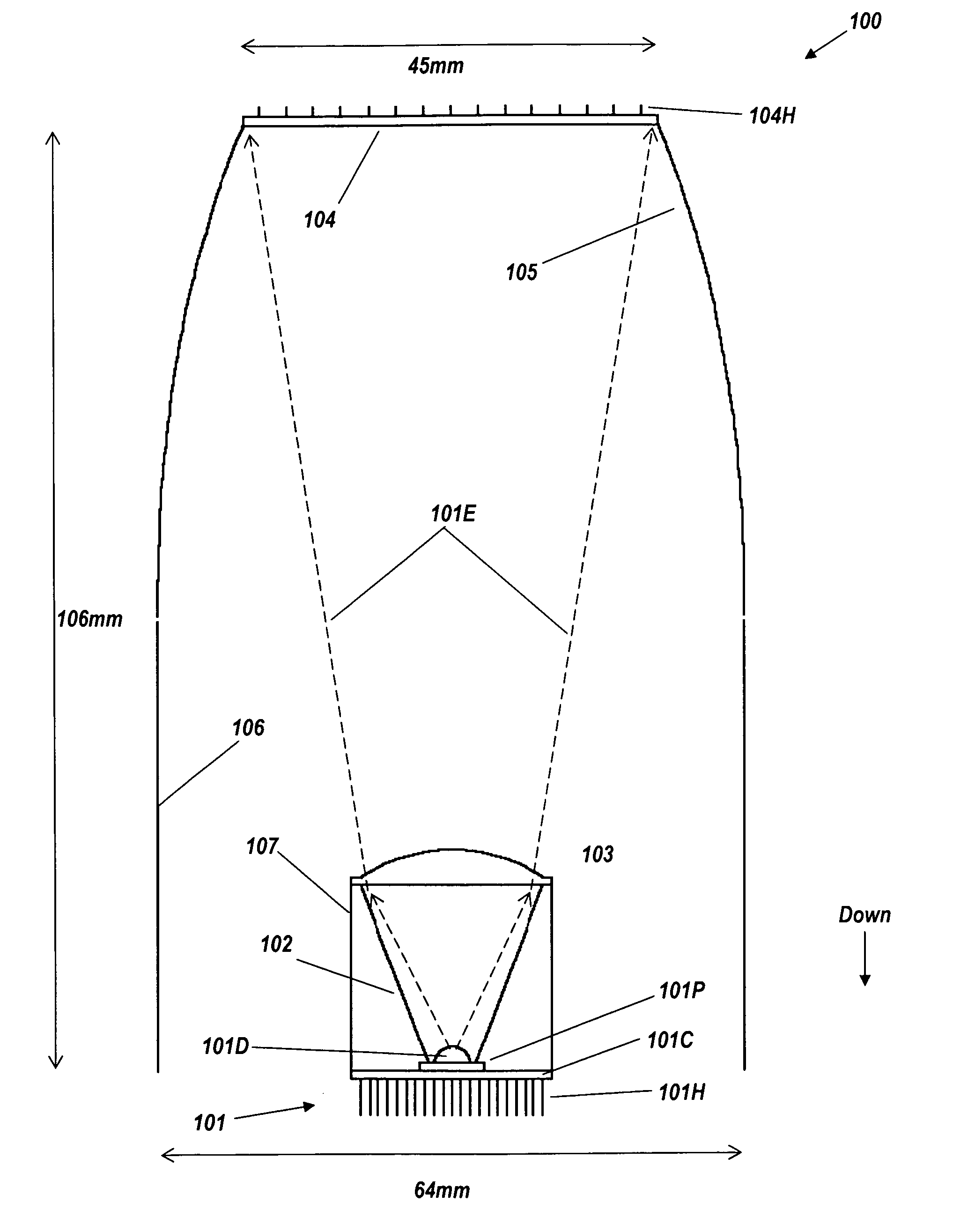
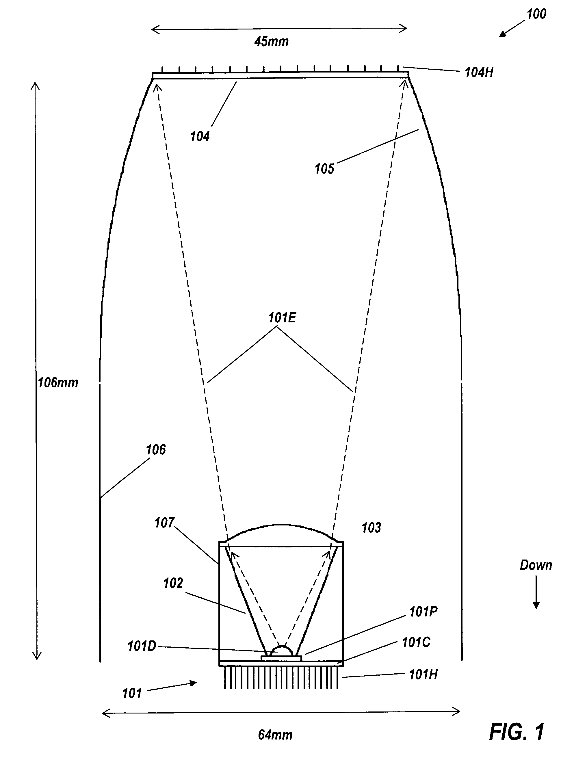
FIG. 1 is a cross-section view of a remote-phosphor LED luminaire 100, comprising light source 101 (comprising transparent dome 101D from which emission 101E originates, LED package 101P, circuit board 101P, and rear heat exchanger 101H), reflective cone 102, plano-convex lens 103, remote phosphor 104, and ideal beam-forming reflector 105. Cylindrical shroud 106 extends downward from reflector 105, to surround cone 102, and has the same reflective coating as reflector 105 to ensure that rays encountering it will stay within the output beam. To ease understanding of the drawing, cylindrical shroud 106 is drawn in FIG. 1 as artificially separated from the profile of reflector 105. However, in a practical embodiment there is no gap between them, and they may be manufactured in a single piece. Cylindrical outer reflector 107 surrounding cone 102 ensures that rays from phosphor 104 or reflector 105, 106 encountering reflector 107 will stay within the output beam. The shroud and reflector...

second embodiment

FIG. 3 is a cross-section view of a remote-phosphor LED downlight. FIG. 3 shows luminaire 300, comprising blue light source 301 (comprising transparent dome 301D, LED package 301P, and rear heat exchanger 301H), conical reflector 302, plano-convex lens 303, remote phosphor 304, and ideal reflector 305, a slightly truncated CPC with a 30° acceptance / output angle. As shown in FIG. 3, cone frustum 302 has an axial length of 21 mm. Lens 303 and the wide end of cone 302 have a diameter of 20 mm. Cone 302 and lens 303 could be replaced by any suitable collimator that produces an output beam no wider in angle than ±30°. Dotted line 304E denotes the emission of remote phosphor 304, confined by reflector 305 to ±30°. Narrower output angles, for example, down to ±20°, are equally feasible if greater overall depth and width are allowed. As shown in FIG. 3, luminaire 300 is 106 mm high, 90 mm wide across the output end, and 45 mm wide across the phosphor end.

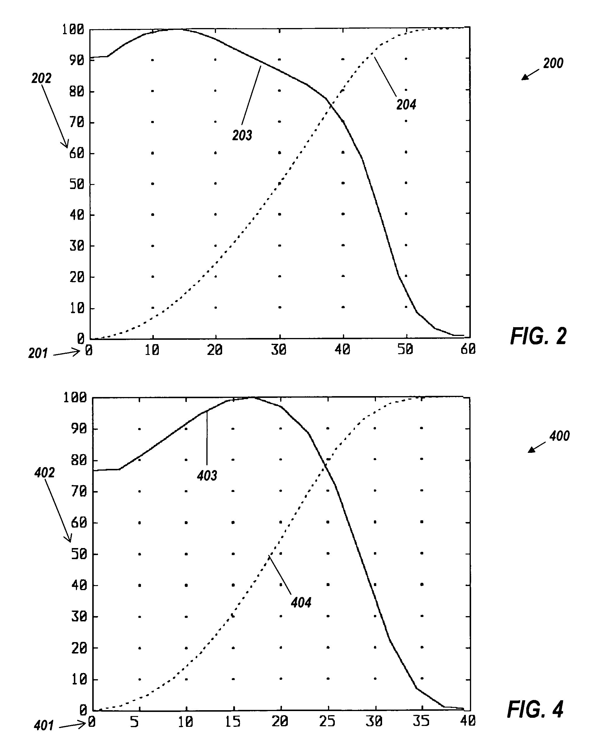
FIG. 4 shows the far-field performan...

third embodiment

FIG. 5 shows a perspective cutaway view of a third embodiment, of a luminaire 500 with some of its key components as it would be seen from below. Remote-phosphor luminaire 500 comprises an outer cylindrical shroud 501, the interior surface of which acts as a reflector, and spider 502 supporting the light engine 503. The light engine 503 comprises conical reflector 503R, plano-convex lens 503L, transparent dome 503D, multi-chip LED package 503P, circuit board 503C, driver module 503D, power wire 503W, and multi-rod heat sink 503H on the underside of the light engine, which is encased in an exterior cylindrical reflector 504. External CPC 504 holds spider 502 and remote phosphor (not shown) with its cylinder-finned heat exchanger 505.

Spider 502 has internal features on one or more of its three vanes (two shown) to enclose the wiring 503W. The arms of spider 502 are preferably sharp-edged on the edge towards the remote phosphor 104, 304 and coated with high-reflectivity material. Light...


PUM


Abstract

An embodiment of a collimating downlight has front-mounted blue LED chips facing upwards, having a heat sink on the back of the LED chips exposed in ambient air. The LED chips are mounted in a collimator that sends their blue light to a remote phosphor situated near the top of the downlight can. Surrounding the remote phosphor is a downward-facing reflector that forms a beam from its stimulated emission and reflected blue light. The phosphor thickness and composition can be adjusted to give a desired color temperature.

Description

BACKGROUND OF THE INVENTIONDownlights are lighting fixtures mounted in a ceiling for illumination directly below them. These ubiquitous luminaires generally comprise an incandescent spotlight mounted within a can. The can is typically closed except at the bottom, so any hot air becomes trapped within the can. Even in the rare cases when heat is transmitted through the can to a heat sink or heat exchanger on the outside of the can, the heat exchanger is typically in stagnant air within a false ceiling, and is not very effective. In most cases, not only is there no heat exchanger, the can is actually insulated to prevent heat from being delivered into the space within the false ceiling. Since incandescent bulbs operate hot anyway, they are not thermally bothered by the can being a trap for hot air. It would be highly desirable to replace the light bulbs with lamps using light-emitting diodes (LEDs), which are more efficient. A white LED system, using blue LEDs combined with yellow pho...

Claims


Application Information

Patent Timeline
Patent Type & Authority Patents(United States)
IPC IPC(8): F21V33/00
CPCF21S8/026F21V7/0008F21V7/0025F21V9/00F21V11/06F21V29/80F21V29/717F21V29/74F21V29/75F21V29/004F21Y2101/02F21K9/64F21Y2115/10
Inventor FALICOFF, WAQIDIPARKYN, WILLIAM A.
Owner SEOUL SEMICONDUCTOR
Learn More