
Method of increasing etchability of metals having chemical etching resistant microstructure

a microstructure and metal technology, applied in the direction of valve housings, engine components, mechanical equipment, etc., can solve the problems of reducing the reliability of the valve, requiring high seating force, and affecting so as to increase the etchability of metals, the effect of easy chemical etching

Inactive Publication Date: 2011-09-13
APPLIED MATERIALS INC
View PDF7 Cites 0 Cited by
  • Summary
  • Abstract
  • Description
  • Claims
  • Application Information

AI Technical Summary

Benefits of technology

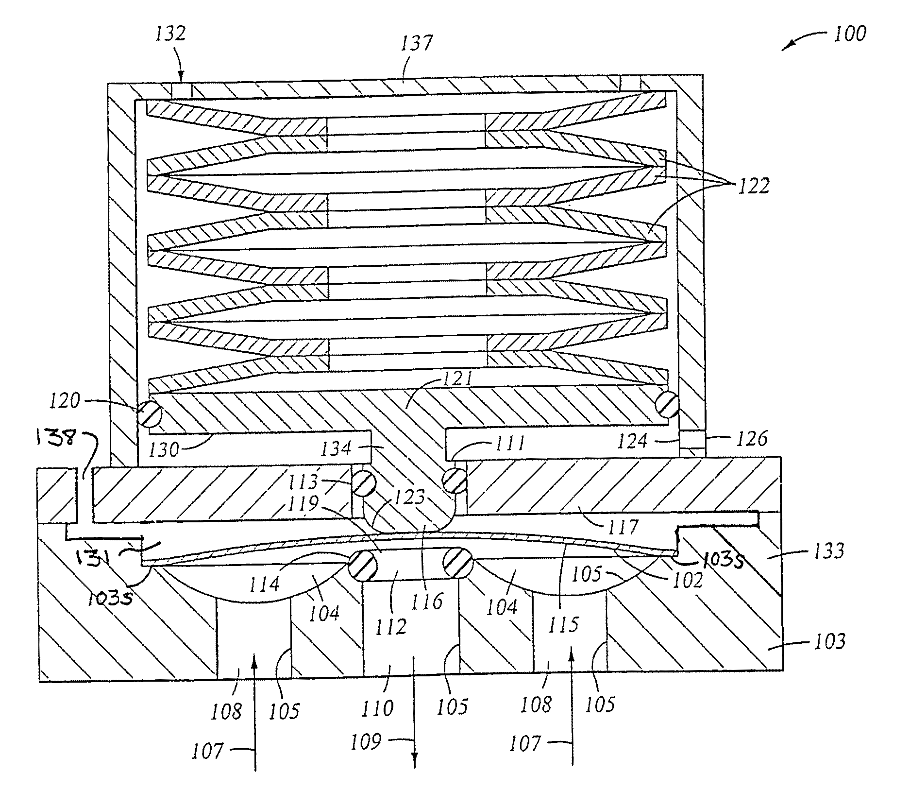
[0014]In the valve's wetted section, metal-to-metal bonding can advantageously be accomplished using diffusion bonding. Diffusion bonding is a direct bonding process which provides strong bonds that do not absorb or release process fluids, and do not contribute impurities to the process fluids, as a welded joint might do. It is important that no adhesive (or adhesive residue) be present on the wetted flow path. Diffusion bonding permits the formation of complex shapes without costly milling (machining).
[0028]Also disclosed herein is a method of increasing the etchability of metals which have a microstructure which is resistant to chemical etching (such as HASTELLOY C-22). This is accomplished by temporarily removing the microstructure which provides corrosion resistance to the metal. The microstructure is removed from the metal by heating the metal to a temperature within the range of about 1800° F. to about 2000° F. for a period of at least a few minutes. The heat-treated metal can be more easily chemically etched than prior to heat treatment. Following chemical etching, the microstructure must be returned to the metal in order for the metal to regain its original corrosion resistance. This is accomplished by heating the metal to a temperature greater than about 2100° F. for at least about 30 minutes, followed by rapid cooling of the metal to a temperature of less than about 300° F., within a time period of about 5 minutes. The second heat treatment step can be performed concurrently with diffusion bonding of two or more layers of the metal. The above method is particularly useful for treatment of corrosion-resistant metal alloys which contain between about 43 to about 71 weight % nickel, and between about 1 to about 30 weight % chromium, by way of example and not by way of limitation.

Problems solved by technology

As a result, all valves with metal valve seats are typically larger in size and cost significantly more than valves with polymeric seats.
However, in previous designs, when the valve seat is metal, a particularly high seating force is required, compared with polymeric valve seats.
Typically, when a plastic seat is used for a high cycle application, plastic deformation of the seat leads to lower valve reliability.
When the actuator design incorporates a spring (or springs) capable of applying the large force required for a metal valve seat, the spring is typically large, on the order of 3 cm to 10 cm tall, and the valve itself is expensive, often costing around 5-6 times the price of a comparable capacity plastic-seated valve.

Method used


Image

  • Method of increasing etchability of metals having chemical etching resistant microstructure
  • Method of increasing etchability of metals having chemical etching resistant microstructure
  • Method of increasing etchability of metals having chemical etching resistant microstructure

Examples


Embodiment Construction

[0054]As a preface to the detailed description, it should be noted that, as used in this specification and the appended claims, the singular forms “a”, “an”, and “the” include plural referents, unless the context clearly dictates otherwise. When the term metal or metallic is used, it is understood that this includes metal alloys. Other terms important to an understanding of the invention are defined in context throughout the application.

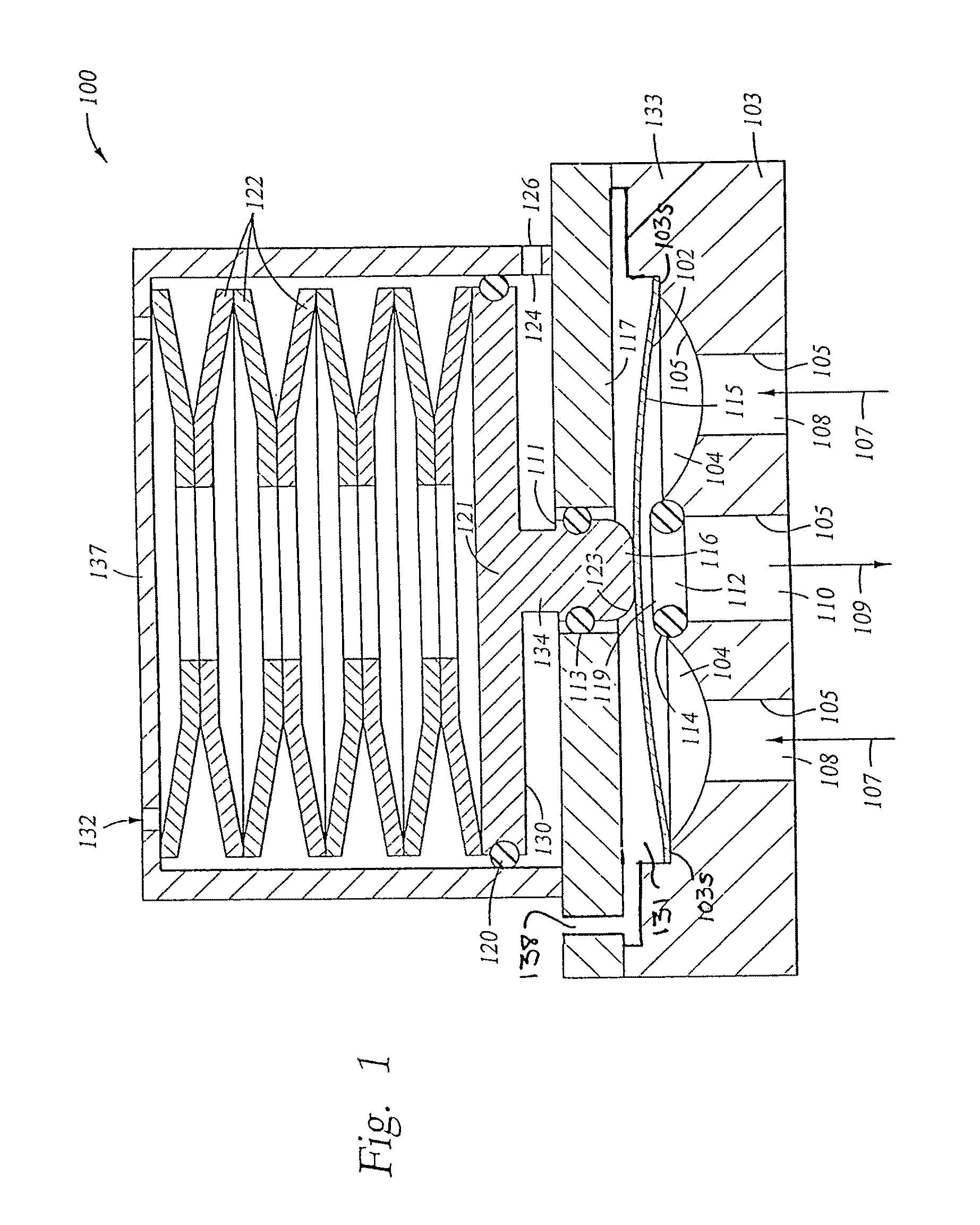
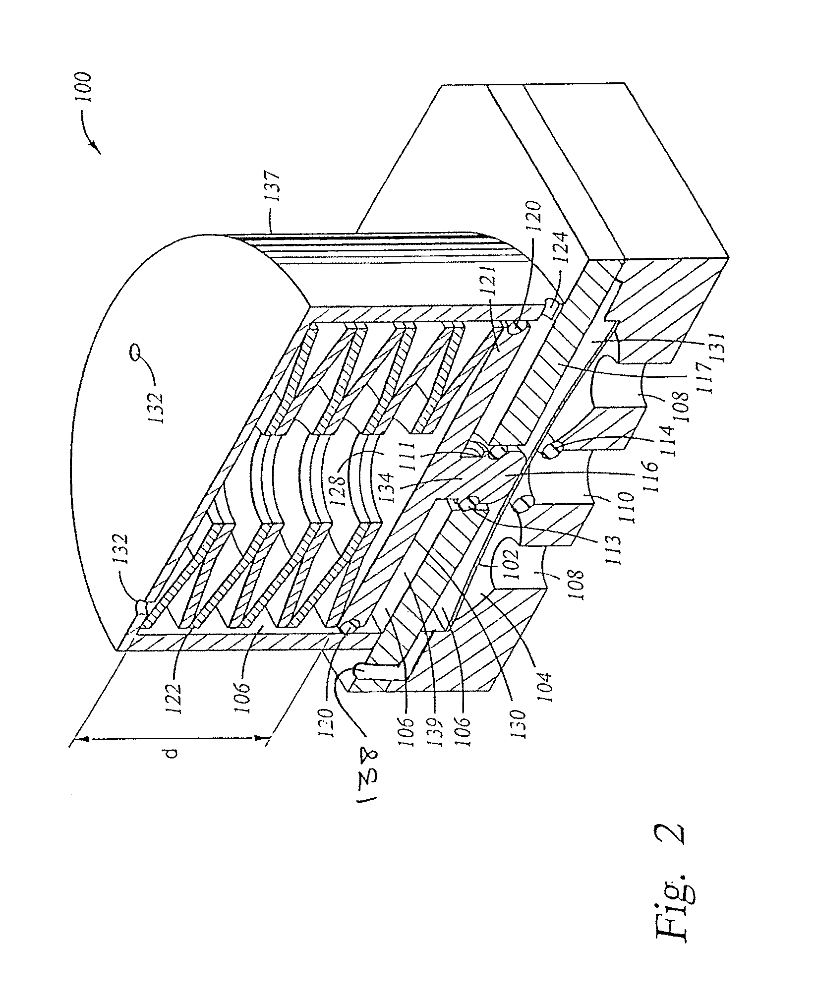
[0055]For purposes of illustration, the first embodiment of a layered structure concept will be described with respect to the design of compact fluid on / off valve where a portion of the compact fluid on / off valve is integrated into a fluid handling network architecture. FIGS. 1 and 2 illustrate one embodiment of a valve 100 which incorporates a number of inventive features. In FIGS. 1 and 2, all of the valve parts which contact (are wetted by) fluid flowing through the valve are metallic. In particular, parts 102, 103, and 114 are wetted parts. Typic...


PUM

PropertyMeasurementUnit
temperatureaaaaaaaaaa

Abstract

A space-conserving integrated fluid delivery system which is particularly useful for gas distribution in semiconductor processing equipment. The invention also includes an integrated fluid flow network architecture, which may include, in addition to a layered substrate containing fluid flow channels, various fluid handling and monitoring components. The layered substrate is diffusion bonded, and the various fluid handling and monitoring components may be partially integrated or fully integrated into the substrate, depending on design and material requirements.

Description

RELATED APPLICATIONS[0001]This application is a divisional application of U.S. application Ser. No. 11 / 788,427, filed Apr. 20, 2007, which is currently pending, which is a continuation application of U.S. application Ser. No. 10 / 617,950, filed Jul. 12, 2003, which is abandoned, which is a continuation-in-part of U.S. application Ser. No. 10 / 328,135, filed Dec. 20, 2002, which issued as U.S. Pat. No. 6,736,370 on May 18, 2004.FIELD OF THE INVENTION[0002]The present invention pertains to a space-conserving integrated fluid delivery system which is particularly useful for gas distribution in semiconductor processing equipment. The present invention also pertains to an on / off valve of compact design, adapted for allowing or preventing the flow of gases in semiconductor processing applications. It also pertains to other integrated fluid components, such as filters, pressure sensors, fluidic thermal sensors, laminar flow elements, pressure regulators, control valves, flow restrictors, and...

Claims


Application Information

Patent Timeline
Patent Type & Authority Patents(United States)
IPC IPC(8): C03C25/68F16K27/00F16K99/00
CPCF16K27/003F16K99/0001F16K99/0015F16K99/0059F16K99/0028F16K2099/0076F16K2099/0074
Inventor CROCKETT, MARKLANE, JOHN W.DECHELLIS, MICAHELMELCER, CHRISPORRAS, ERICAKHULLAR, ANEESHMOHAMMED, BALARABE N.
Owner APPLIED MATERIALS INC
Learn More