
Sputtering target for forming protective film and laminated wiring film

a technology which is applied in the direction of vacuum evaporation coating, transportation and packaging, coatings, etc., can solve the problems of increased manufacturing cost of sputtering target and laminated film, difficult to use laminated film as wiring film, and large cost of liquid waste treatment, etc., to suppress the generation of non-molten residue, suppress weather resistance, and suppress the effect of discoloration

Active Publication Date: 2017-01-10
MITSUBISHI MATERIALS CORP
View PDF33 Cites 0 Cited by
  • Summary
  • Abstract
  • Description
  • Claims
  • Application Information

AI Technical Summary

Benefits of technology

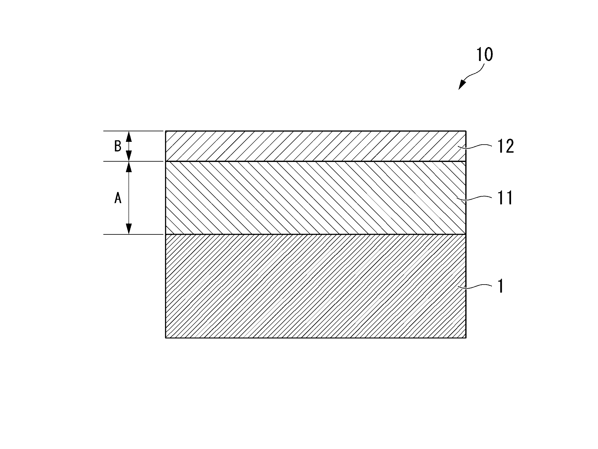
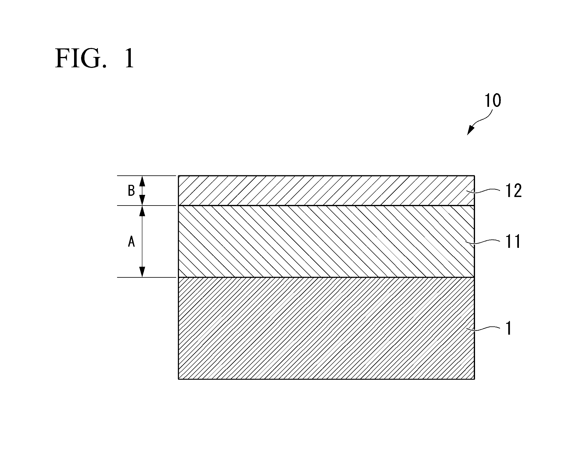
The present invention provides a sputtering target for forming protective film that has excellent weather resistance, can prevent surface discoloration, has favorable etchability, and obtains a tapered shape after being etched. Additionally, the invention also provides a laminated wiring film with a protective film formed using the sputtering target.

Problems solved by technology

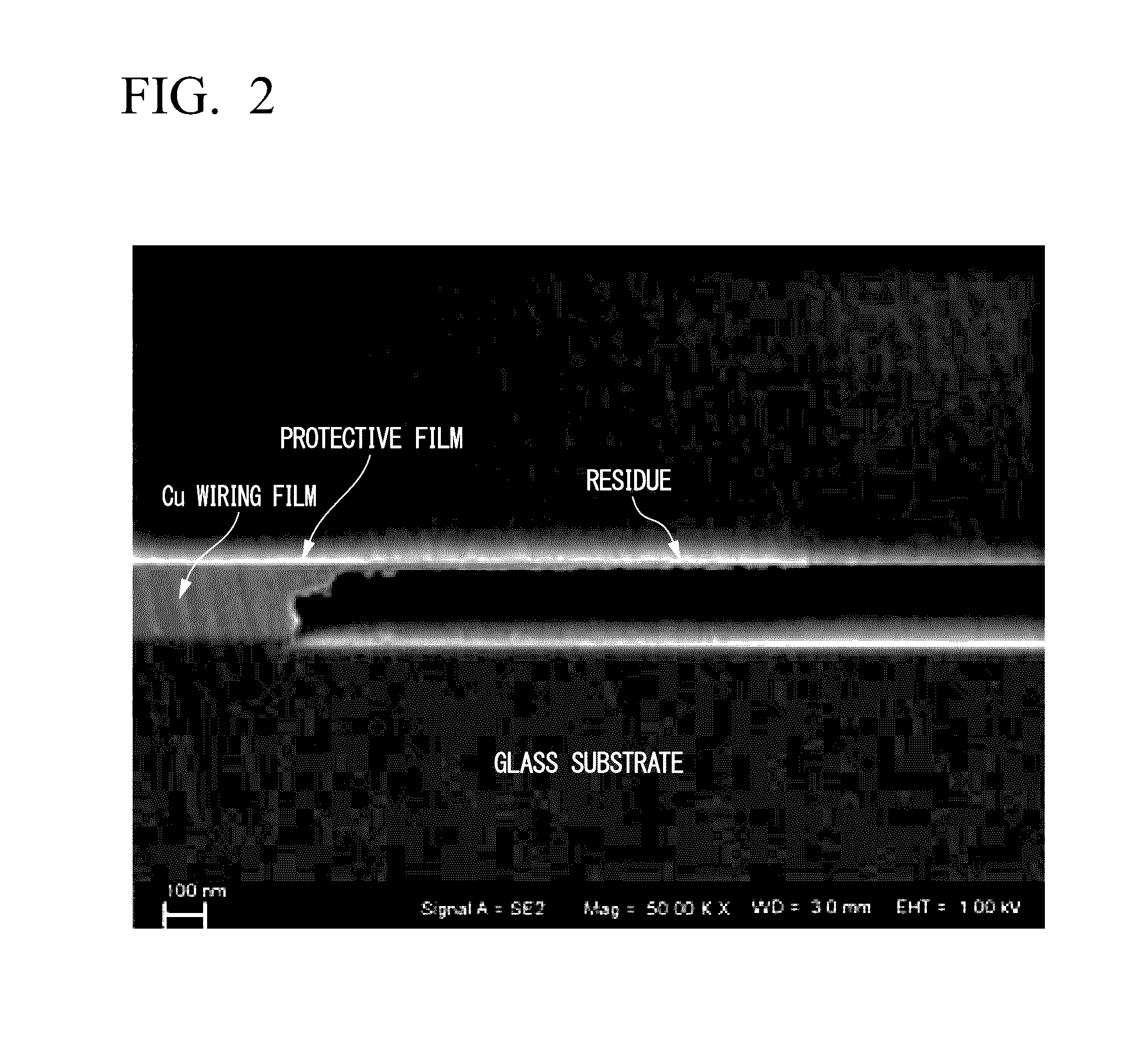
Since there was a concern that the residue might short-circuit wires, it was difficult to use the laminated film as a wiring film.
In addition, in a case in which the laminated film contained Cr, a liquid waste after etching also contained Cr, and thus there was a problem in that a sizeable cost was required to treat the liquid waste.
Furthermore, since the laminated film contained a large amount (35 to 84.5% by mass) of relatively expensive Ni, there was a problem in that the manufacturing cost of a sputtering target and a laminated film increased.
In a case in which the shape of the cross-section of the etched wires became a rectangular shape or a reverse tapered shape, there was a concern that defects called voids might be generated in the edge portion of the Cu wiring film, the wires might be cut while stacking layers and the yield and the quality might be degraded.

Method used


Image

  • Sputtering target for forming protective film and laminated wiring film
  • Sputtering target for forming protective film and laminated wiring film
  • Sputtering target for forming protective film and laminated wiring film

Examples


examples

[0064]Hereinafter, the effects of the sputtering target for forming protective film and the laminated wiring film according to the present invention will be evaluated, and the results of evaluation tests will be described.

[0065]

[0066]An ingot of oxygen-free copper with a purity of 99.99% by mass was prepared, and hot rolling at 800° C., steel relief annealing and mechanical work were carried out on the ingot, thereby producing pure copper target for forming Cu wiring film with dimensions of an outer diameter of 100 mm and a thickness of 5 mm.

[0067]Next, an oxygen-free copper backing plate was prepared, the pure copper target for forming Cu wiring film was laid on the oxygen-free copper backing plate, and soldered by using indium at a temperature of 200° C., thereby producing a backing plate-attached target.

[0068]

[0069]Oxygen-free copper (purity: 99.99% by mass), aluminum (purity: 99.99% by mass), commercial pure iron (purity: 99% by mass), low carbon nickel (purity: 99.9% by mass) a...


PUM

PropertyMeasurementUnit
temperatureaaaaaaaaaa
thicknessaaaaaaaaaa
thicknessaaaaaaaaaa

Abstract

A sputtering target for forming protective film according to the invention is used to form protective film on one surface or both surfaces of a Cu wiring film, and includes 8.0 to 11.0% by mass of Al, 3.0 to 5.0% by mass of Fe, 0.5 to 2.0% by mass of Ni and 0.5 to 2.0% by mass of Mn with a remainder of Cu and inevitable impurities. In addition, a laminated wiring film includes a Cu wiring film and protective film formed on one surface or both surfaces of the Cu wiring film, and the protective film is formed by using the above sputtering target.

Description

BACKGROUND OF THE INVENTION[0001]Field of the Invention[0002]The present invention relates to a sputtering target for forming protective film which is used when forming protective film that protect a Cu wiring film including copper or a copper alloy, and a laminated wiring film including a protective film formed by using the sputtering target for forming protective film.[0003]The present application claims the right of priority to Japanese Patent Application No. 2013-027046 filed on Feb. 14, 2013 in Japan, and the contents thereof are incorporated herein by reference.[0004]Description of Related Art[0005]In the past, Al was widely used in wiring film for flat panel displays such as liquid crystal or organic EL, panels or touch panels. In recent years, an attempt has been made to reduce the size (width) and thickness of wiring film, and there has been a demand for wiring film with a lower resistivity than those in the past.[0006]As the size and thickness of wiring film are reduced, w...

Claims


Application Information

Patent Timeline
Patent Type & Authority Patents(United States)
IPC IPC(8): B32B15/20H01J37/34H05K3/02H05K1/09H05K3/06
CPCH01J37/3426H05K3/022H05K1/09H05K3/06H05K2201/0317H05K2201/0338Y10T428/1291C22C9/01C23C14/34
Inventor MORI, SATORUNONAKA, SOUHEI
Owner MITSUBISHI MATERIALS CORP
Learn More