Head gimbal assembly for use in disk drive devices and method of making the same

a disk drive device and head gimbal technology, applied in the direction of data recording, magnetic recording, instruments, etc., can solve the problems of affecting the ability of the read/write head to accurately read data, the edge of the slider may hit the pzt element, and the use of known technology becomes more and more difficult to quickly and accurately position the read/write, etc., to achieve the effect of improving the overall performan

Active Publication Date: 2011-09-13
SAE MAGNETICS (HK) LTD
View PDF10 Cites 2 Cited by
  • Summary
  • Abstract
  • Description
  • Claims
  • Application Information

AI Technical Summary

Benefits of technology

[0016]Still another aspect of certain example embodiments described herein relates to substantially balanced weight between the head and tail portions of the tongue region of the suspension flexure.
[0017]It will be appreciated that these aspect may be used separately or in various combinations, all of which may help to improve overall performance.

Problems solved by technology

As track density increases, it becomes more and more difficult using known technology to quickly and accurately position the read / write head over the desired information tracks on the storage media.
Because of the inherent tolerances (e.g., dynamic play) of the VCM and the head suspension assembly, the slider cannot achieve quick and fine position control, which adversely impacts the ability of the read / write head to accurately read data from and write data to the disk when only a servo motor system is used.
Unfortunately, when a vertical vibration or other shock occurs (e.g. when a “tilt-drop” shock occurs), the slider is rotated against the dimple and the leading edge of the slider may hit the PZT element.
The PZT element may suffer damage, such as, for example, a crack or a break.
This arrangement thus raises reliability concerns, for example, with respect to the PZT elements.
This contact, brought about by the occurrence of a shock for example, may damage the thin-film PZT element.
Accordingly, the PZT element will be damaged.

Method used


Image

  • Head gimbal assembly for use in disk drive devices and method of making the same
  • Head gimbal assembly for use in disk drive devices and method of making the same
  • Head gimbal assembly for use in disk drive devices and method of making the same

Examples


Embodiment Construction

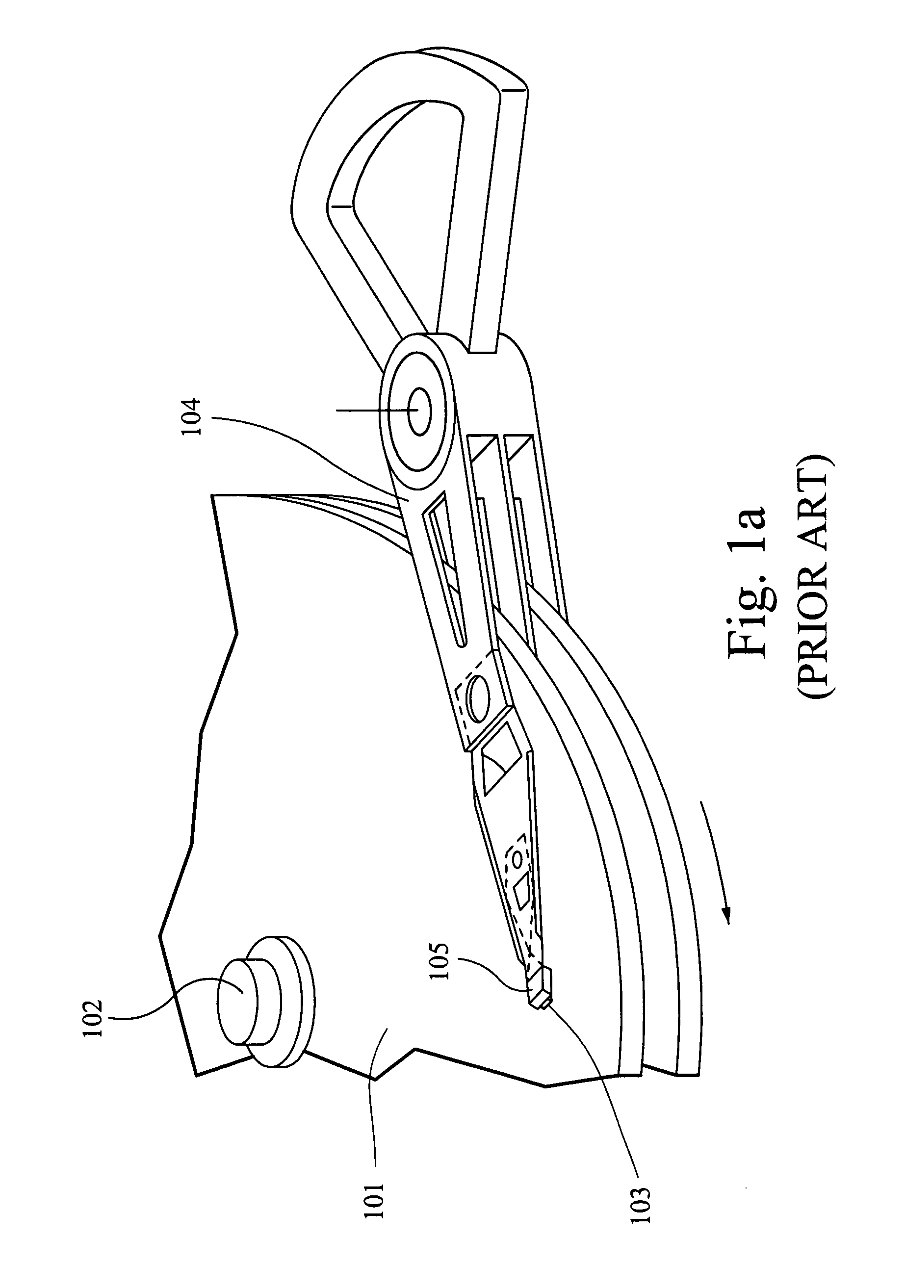
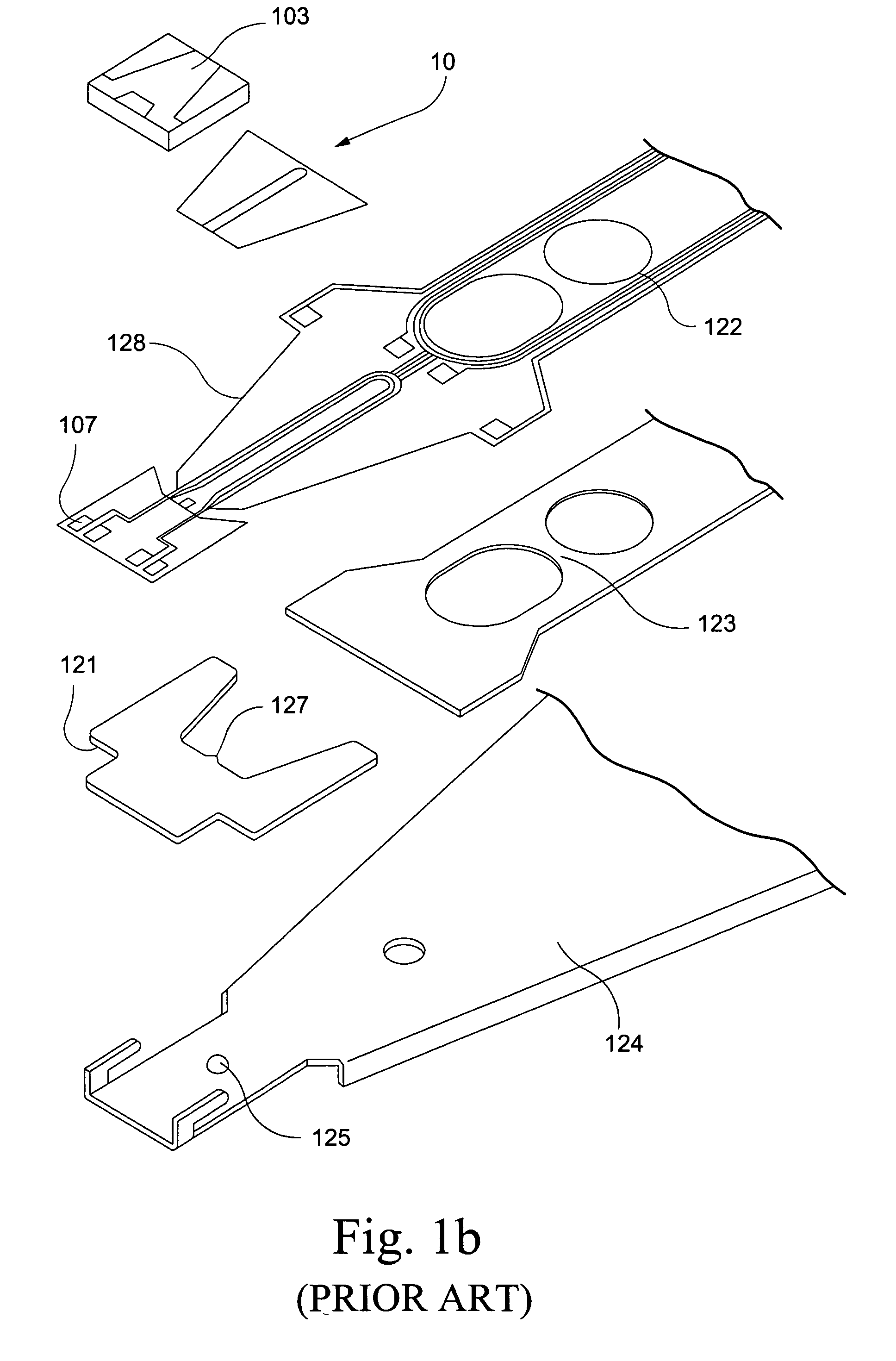
[0041]A conventional HGA has a large suspension tongue region and requires a parallel gap. However, as noted above, this arrangement enables the PZT element(s) to be damaged easily. Accordingly, certain example embodiments may reduce the size of the tongue region, reduce and / or eliminate the need for a gap, and / or provide performance even when shocks occur.

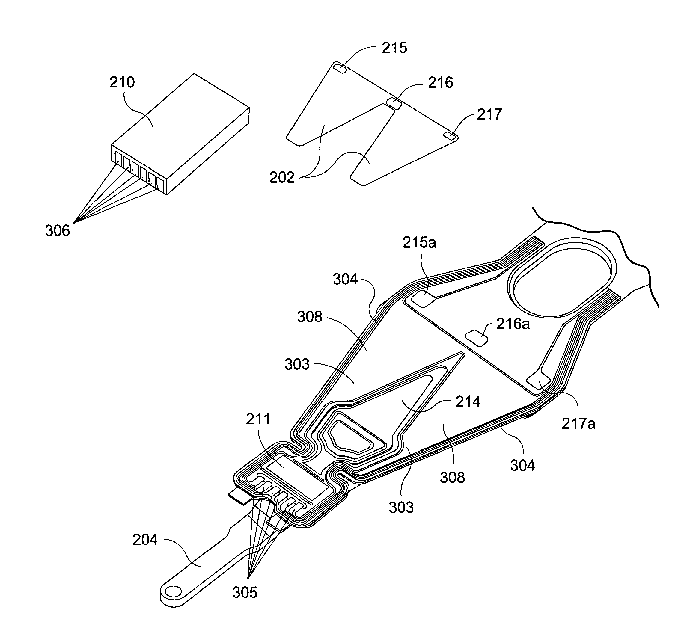
[0042]FIG. 2a is a perspective view of an HGA having a thin-film PZT micro-actuator, in accordance with an example embodiment. The HGA 200 of FIG. 2a includes a load beam 204, a flexure 209, a hinge 213, and a base plate 212. A slider 210 is at least partially mounted on the top region of the tongue of the flexure 209 and bottom region of the tongue of the flexure 209. There are two PZT elements 202 mounted on the middle region of the flexure 209.

[0043]FIG. 2b is a more detailed view of the tongue region of FIG. 2a, in accordance with an example embodiment; and FIG. 2c is a side view of the tongue region of FIG. 2a, in accordance ...


PUM

PropertyMeasurementUnit
rigidityaaaaaaaaaa
widthaaaaaaaaaa
weightaaaaaaaaaa

Abstract

Systems and methods for accurate position adjustment of thin-film PZT micro-actuators are provided. In certain example embodiments, a head gimbal assembly is provided. A suspension includes a suspension flexure located at one end of the suspension, and the suspension flexure includes a tongue region. At least one micro-actuator is mounted to a micro-actuator mounting region of the tongue region of the suspension flexure. Any gap between the slider and the at least one micro-actuator may be reduced and / or eliminated. A slider is substantially fully mounted on an insulating layer, and the insulating layer separates the slider from the at least one micro-actuator. The suspension flexure may be located substantially fully underneath the slider, and the tongue region of the suspension flexure may be substantially equally weighted around a dimple formed on the suspension. The rigidity of the suspension flexure may be increased by one or more supports formed thereon.

Description

FIELD OF THE INVENTION[0001]The example embodiments herein relate to information recording disk drive devices and, more particularly, to improved head gimbal assemblies (HGAs) that allow for more accurate position adjustment of thin-film PZT micro-actuators, and / or methods of making the same.BACKGROUND OF THE INVENTION[0002]One known type of information storage device is a disk drive device that uses magnetic media to store data and a movable read / write head that is positioned over the media to selectively read from or write to the disk.[0003]Consumers are constantly desiring greater storage capacity for such disk drive devices, as well as faster and more accurate reading and writing operations. Thus, disk drive manufacturers have continued to develop higher capacity disk drives by, for example, increasing the density of the information tracks on the disks by using a narrower track width and / or a narrower track pitch. However, each increase in track density requires that the disk dr...

Claims


Application Information

Patent Timeline
Patent Type & Authority Patents(United States)
IPC IPC(8): G11B5/48G11B21/16
CPCG11B5/5552G11B5/60
Inventor YAO, MINGGAO
Owner SAE MAGNETICS (HK) LTD
Why Eureka
Try Eureka