
Closed loop, hot dry rock heat recovery process

Inactive Publication Date: 2011-09-20
GEOTHERMIC SOLUTION
View PDF9 Cites 20 Cited by
  • Summary
  • Abstract
  • Description
  • Claims
  • Application Information

AI Technical Summary

Benefits of technology

[0021]Yet another object of the invention is to provide a system which maximizes heat recovered in hot dry rock geothermal systems by increasing heat recovery volume in a formation at a single well or shaft.
[0024]The choice of heat recovery fluid is selected to minimize cost per unit length of installed conduits and installed heat transfer surface required at a terminal end heat exchanger to obtain the objects of economic heat recovery from a geological formation. Pumping energy required for returning condensed and cooled heat recovery fluid from electrical energy production steps to the terminal end heat exchanger by way of the downflow conduit is also minimized.
[0029]An object of the invention is to provide a heat recovery fluid which reduces the cost and complexity of a closed loop, hot dry rock heat recovery system for a geological formation at from 4,000 to 10,000 meters depth from the surface.

Problems solved by technology

A disadvantage with current, installed technology for geothermal heat recovery in that many geothermal are operated with excessive injection of fluids to recover the heat and thereby cool the resource.
Conservative management to avoid such a result results in a failure to recover substantial heat resources.
Current, installed technologies suffer a further disadvantage, in that injection of fluids, both liquid and gas, into the geological formation necessarily disrupts to a greater or lesser degree the structure of the formation.
The disruption can result in surface subsidence and / or a severe re-structuring of the formation in a manner that impairs the heat resource.
Therefore, current, installed technologies substantially endanger the heat resource they attempt to recover.
A fourth technology has not been extensively practiced, in that the depth at which geothermal heat is recovered exceeds those of the above technologies.
Such continuous and violent expansion of gases in the vicinity of injection conduits can result in damage to natural flow paths of gases within the formation, potentially closing off wells drilled to recover the vaporized liquids.
Geothermal formations can provide heat for many decades but using injection-dependent heat recovery technologies can eventually cause a geological formation to cool down to temperatures below which energy production is no longer feasible.
Predictive calculations for depletion of heat from a specific location are not presently absolutely accurate, meaning that recovery of investment using injection technologies is necessarily more risky that using a more controllable and predictable closed loop, hot dry rock system.
Some geothermal power plant capital costs are generally constant regardless of the technology and include the cost of land and physical plant, including buildings and power-generating turbines.
Resistance to installation of closed loop, hot dry rock systems has been based primarily on an installed cost of prior art devices and equipment to reach deeper geological formations.
A closed loop, hot dry rock system which reduces such aspects as pipe diameters and conduit cost per unit length can dramatically affect the overall cost of the project, considering the depths which will be typically reached by the terminal end heat exchangers of the system.
Even now, there is a strain on our ability to deliver such energy.
In addition, economics limit the operation pressure.

Method used


Image

  • Closed loop, hot dry rock heat recovery process
  • Closed loop, hot dry rock heat recovery process
  • Closed loop, hot dry rock heat recovery process

Examples


Embodiment Construction

[0035]The invention is now discussed with reference to the figures.

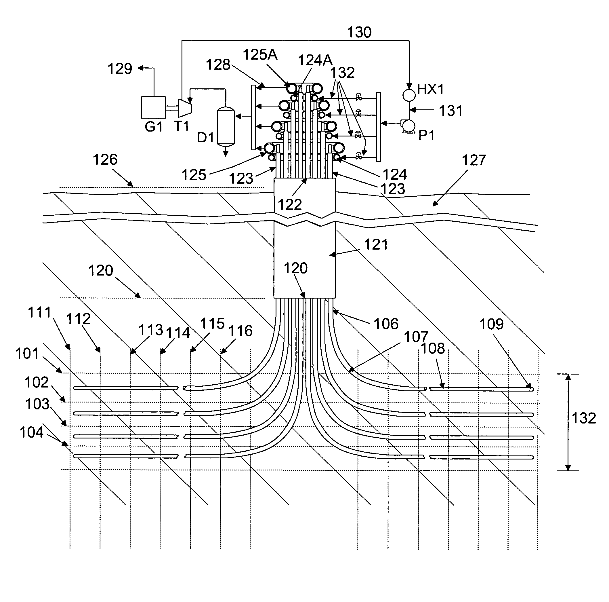
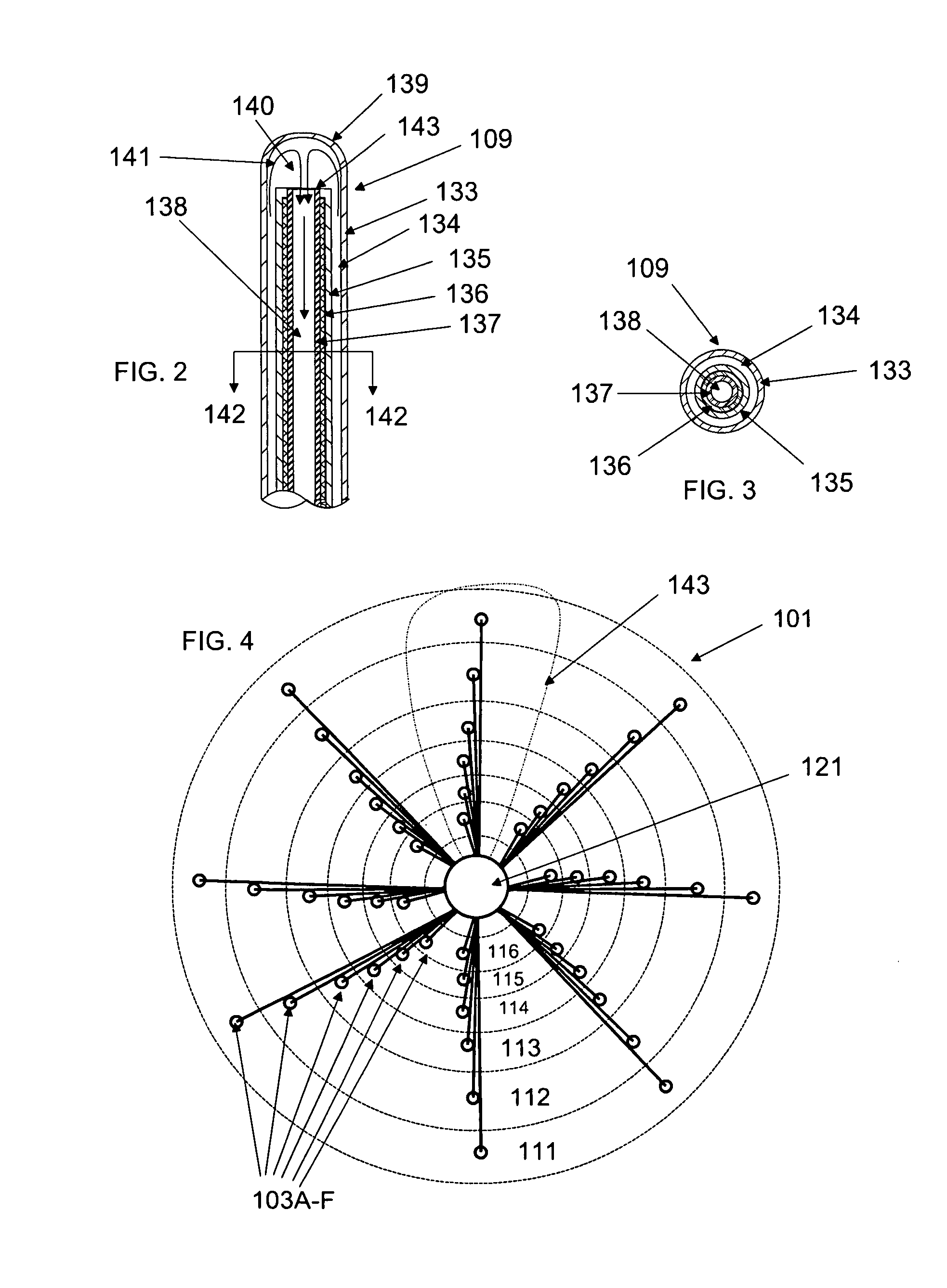
[0036]FIG. 1 is a cutaway side view of a formation 127 having drilled into it a cylindrical central shaft 121 extending from a top opening 122 above surface 126 to a lower end 120. The central shaft comprises a metal and cement shell and defines a large diameter bore for protection and direction of individual bore pipes 106 which extend from top ends 123 above top opening 122 through bottom or side (not shown) openings in central shaft 121 to bend sections 107. Bend sections 107 further extend to generally horizontal sections 108 and terminate at terminal ends 109. Four or more bore pipes 106 extend radially and generally horizontally from central shaft 121 defining thereby a top heat recovery level 101, middle heat recovery levels 102 through 103, and bottom heat recovery level 104. Further, each of the heat recovery levels 101 through 104 are divided in defined radial sections 111 through 116. All the heat recovery...


PUM


Abstract

The present invention is a closed loop system of heat recovery in hot dry rock or in water-containing formations for generation of electrical power. Recovery of heat from such formations is accomplished by way of multiple horizontal levels of generally radially drilled bores from a central shaft. Heat transfer is accomplished either by way of terminal end heat exchangers or by way of heat transfer to conduits extending from the central shaft.

Description

FIELD OF THE INVENTION[0001]The present invention relates to a closed loop, hot dry rock system of heat recovery from geological formations for production of other forms of energy.BACKGROUND OF THE INVENTION[0002]Recovery of heat from underground resources is currently commercially practiced in one of three main technological areas, i.e., power plants using dry steam, flash steam, and binary systems. Factors controlling selection of one of these technologies for a selected site include temperature, depth, and quality of the water and steam in the area. In all these cases, condensed steam and / or geothermal fluid is injected back into the ground to recover heat. In some locations, a natural supply of water produces steam from magma deposits is exhausted and processed waste water may be injected to replenish the supply.[0003]A disadvantage with current, installed technology for geothermal heat recovery in that many geothermal are operated with excessive injection of fluids to recover t...

Claims


Application Information

Patent Timeline
IPC IPC(8): F03G7/00
CPCF03G7/04F24T10/17F24T2010/56Y02E10/10
Inventor ZAKIEWICZ, BOHDAN
Owner GEOTHERMIC SOLUTION
Learn More