Electronic throttle control device in V-type internal combustion engine for vehicle

a technology of electronic throttle control and internal combustion engine, which is applied in the direction of machines/engines, combustion-air/fuel-air treatment, and feed systems, etc., can solve the problems of difficult size reduction of internal combustion engine, and achieve the effect of improving maintainability and reducing siz

Active Publication Date: 2011-09-20
HONDA MOTOR CO LTD
View PDF14 Cites 4 Cited by
  • Summary
  • Abstract
  • Description
  • Claims
  • Application Information

AI Technical Summary

Benefits of technology

[0007]It is accordingly an object of the present invention to provide an electronic throttle control device in a V-type internal combustion engine for a vehicle, which can be improved in maintainability and can be reduced in size.
[0013]According to the first aspect of the present invention, the throttle driving motor is located outside the region surrounded by all of the throttle bodies that are respectively connected to all of the intake ports as viewed in plan. Accordingly, the maintenance of a throttle valve driving system can be performed easily and efficiently without interference with the nearest throttle body. Furthermore, an intake passage can be made substantially straight due to the specific location of the throttle driving motor, so that an intake resistance can be reduced to improve the charging efficiency of intake air.
[0014]According to the second aspect of the present invention, all of the fuel injection valves are located inside the above region surrounded by the throttle bodies 10 that respectively connected to all of intake ports 9 as viewed in plan. Accordingly, a fuel supply line for supplying fuel to all of the fuel injection valves can be reduced in length and simplified in structure.
[0015]According to the third aspect of the present invention, all of the throttle valves can be driven by a single throttle driving motor. Accordingly, the structure of the throttle valve driving system can be simplified, and the cost therefor can be reduced.
[0016]According to the fourth aspect of the present invention, at least one throttle valve in the first bank is driven by the first throttle driving motor, and at least one throttle valve in the second bank is driven by the second throttle driving motor. Accordingly, at least one cylinder in either the first bank or the second bank can be put into an inoperative condition as required. Furthermore, the link for connecting the first throttle shaft and the second throttle shaft can be omitted to thereby simplify the connecting mechanism and to reduce the cost.
[0017]According to the fifth aspect of the present invention, at least one throttle valve in the first bank is driven by the first throttle driving motor, and at least two throttle valves in the second bank are individually driven by the respective second throttle driving motors. Accordingly, all of the cylinders can be individually put into an inoperative condition as required. Alternatively, the outputs from all of the cylinders can be individually controlled, thereby improving fuel economy.

Problems solved by technology

Accordingly, there is a possibility that an air cleaner for supplying air through the throttle valves into the cylinders may interfere with the throttle driving motor, which is located at a high position, and a large-diameter input gear of the speed reduction gear train.
Therefore, the air cleaner is spaced apart from a cylinder head cover of the internal combustion engine, causing a problem in that a size reduction of the internal combustion engine is difficult.

Method used


Image

  • Electronic throttle control device in V-type internal combustion engine for vehicle
  • Electronic throttle control device in V-type internal combustion engine for vehicle
  • Electronic throttle control device in V-type internal combustion engine for vehicle

Examples


Embodiment Construction

[0029]The present invention will now be described in detail with reference to the accompanying drawings, wherein the same reference numerals will be used to identify the same or similar elements throughout the several views. It should be noted that the drawings should be viewed in the direction of orientation of the reference numerals.

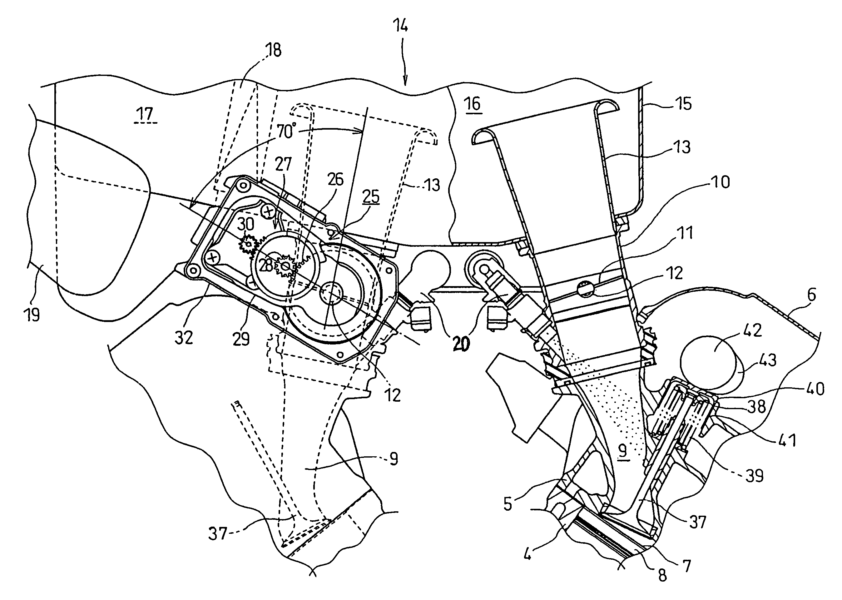
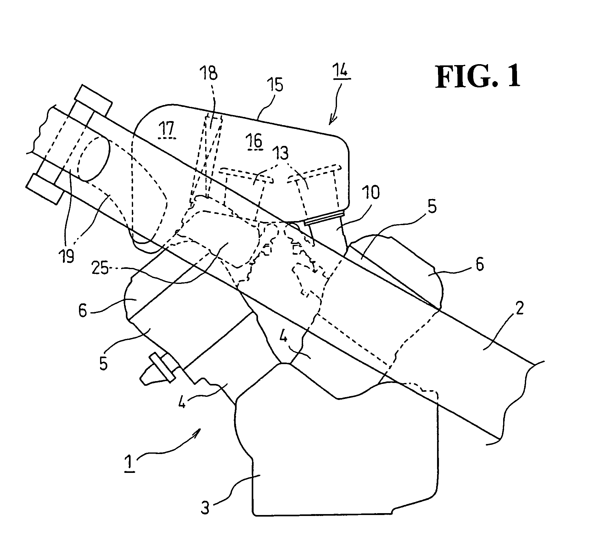
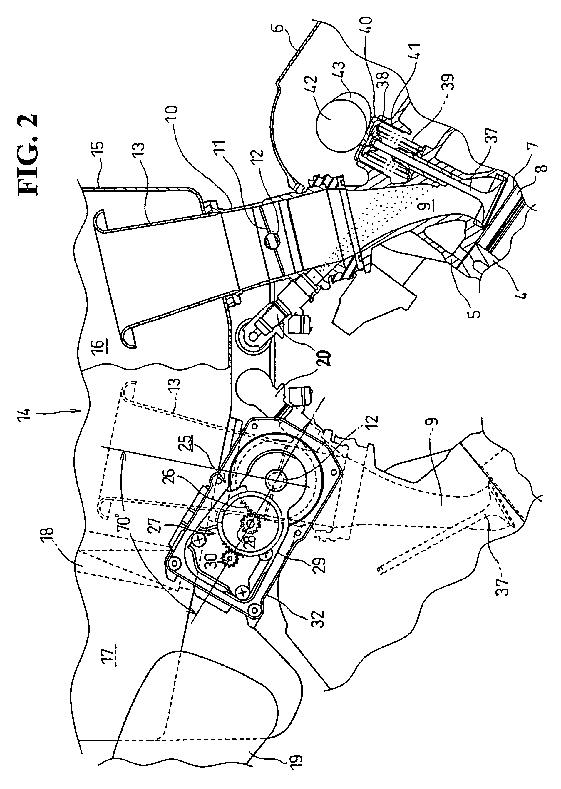
[0030]A first preferred embodiment of the present invention will now be described with reference to FIGS. 1 to 6. Reference numeral 1 generally identifies a V-type internal combustion engine mounted on a motorcycle. The V-type internal combustion engine 1 is a longitudinal V-type four-cylinder internal combustion engine having a front bank and a rear bank. The V-type internal combustion engine 1 is fixedly mounted through brackets (not shown) or the like to a pair of right and left main frames 2 of the motorcycle. The V-type internal combustion engine 1 has a crankcase 3. A front train of two cylinders 4 form the front bank projecting obliquely upward ...


PUM


Abstract

An electronic throttle control device in a internal combustion engine for a vehicle can be improved in maintainability and can be reduced in size. An electronic throttle control device in a V-type internal combustion engine for a vehicle has a fuel injection valve and throttle valves in an intake passage. A throttle driving motor controls the opening angle of each throttle valve according to the amount of operation of a throttle grip performed by an operator of the vehicle. The throttle driving motor is located outside a region surrounded by the throttle bodies that are respectively connected to all of intake ports as viewed in plan.

Description

CROSS-REFERENCE TO RELATED APPLICATIONS[0001]This nonprovisional application claims priority under 35 U.S.C. §119(a) on Patent Application No. 2006-270000, filed in Japan on Sep. 29, 2006, entirety of which is incorporated herein by reference.BACKGROUND OF THE INVENTION[0002]1. Field of the Invention[0003]The present invention relates to an electronic throttle control device in a V-type internal combustion engine for a vehicle. More particularly, the present invention relates to an electronic throttle control device, wherein the amount of operation of the throttle by an operator of the vehicle is electrically detected by a sensor. Also, an electrical output based on a detection signal from the sensor is fed through a wire to a throttle driving motor provided in the vicinity of a throttle valve, whereby the opening angle of the throttle valve is controlled by the power from the throttle driving motor.[0004]2. Background of the Invention[0005]In an internal combustion engine for a veh...

Claims


Application Information

Patent Timeline
Patent Type & Authority Patents(United States)
IPC IPC(8): F02D11/10
CPCF02D9/107F02D9/1095F02D11/10F02M35/10032F02M35/10111F02M35/10216F02M35/10255F02M35/116
Inventor MAEHARA, HAYATOHOTTA, KAZUHITOTSUKUI, TAKAAKIURABE, MASANOBU
Owner HONDA MOTOR CO LTD
Why Eureka
Try Eureka