Collapsible airfoil for trucks and trailers

a truck and trailer technology, applied in the field of truck and trailer collapsible airfoil, can solve the problems of not meeting the necessary conditions unable to meet the design requirements of a working device, increasing the length of the trailer, etc., to reduce the consumption of fuel, minimize the effect of wake, and minimize drag and turbulen

Inactive Publication Date: 2011-09-27
KRON STEVEN TODD
View PDF21 Cites 47 Cited by
  • Summary
  • Abstract
  • Description
  • Claims
  • Application Information

AI Technical Summary

Benefits of technology

[0015]The purpose of the device is to minimize drag and turbulence occurring at the rear of a semi trailer, in order to reduced the consumption of fuel by a semi tractor. This is accomplished using directionally flexible panels consisting of composite material, which are hinged on either side of the trailer via the existing door hinges. These main panels form a contour ending in a wedge at the rear of the device, a shape established by additional panels hinged on the top and bottom of either door, and reinforced by the pressure these additional panels exert against the main body of the device.
[0016]The basic form of the device is such that it fits the full profile of the trailer doors, then tapers inward towards a terminating edge. These contours, as defined by the top and bottom panels through the pressure they exert against the vertical panels, create a teardrop shape, as viewed from the dorsal or ventral perspective. This teardrop shape minimizes the effect of the wake created by the void present behind a moving trailer, causing air to flow smoothly towards the center and effectively eliminating any such vacuum.
[0017]As a result of this tapered contour, airflow converges at the trailing edge of the device. Since the collision of air volumes flowing from either side of the device would cause continued turbulence, this airflow is separated by another panel fastened to the end of the main body via a hinge. This additional panel, referred to as the wake separator, extends along the edge at which left and right sections of the device are joined during deployment, in order to maintain separation between conflicting columns of air from either side of the trailer. An additional wake separator attached to the bottom of the device performs a similar function, but will also facilitate collapse in the event of a rear end collision.

Problems solved by technology

While a wide variety of devices would allow limited use of the doors, only a handful of designs can completely satisfy this condition.
None of these designs, however, satisfy the necessary conditions of a working device.
Not only would this design increase the length of the trailer without increasing cargo capacity, but such curved doors could not close completely, prohibiting temperature control or other advantages associated with conventional cargo containers.
These devices could not easily be retrofitted to an existing cargo container.
While the drag reducing fairing of U.S. Pat. No. 4,458,936 exhibits a shape similar to the present invention, its construction is completely different and its use ultimately impractical.
While it is suggested that this rear fairing could be readily detached, this process would prove impractical, particularly as removal need be regularly performed.
Not only would such a device be rigid and uncollapsible, but with a volume as large as 150 cubic feet, its dimensions would make it unmanageable.
Since the removal and replacement of any such fairing would be inordinately complicated and time consuming, this type of device must remain attached.
A percentage of prior art is designed with this requirement chiefly in mind, but consequently lacks the preferred contour present in other aerodynamic apparatuses.
Whether deployed or collapsed, these panels are always flat, and as such cannot form the preferred contour.
While such a shape is easily folded to fit with the door, these panels merely modify the existing shape of the trailer rather than transform it.
Such a configuration is insufficient to eliminate the partial vacuum present at the rear of the trailer during transit or its deleterious effects on fuel economy.
While this configuration creates a more aerodynamic contour than similar devices, it suffers from a fatal flaw.
The difficulty of docking is compounded by a related deficiency, that these panels could not be folded back onto themselves and as a result extend beyond the length of the swing doors, making their opening and closing cumbersome or hazardous.
Due to their insubstantial construction, these devices would be unstable under the highway conditions at which they would otherwise yield their greatest benefit.
In such a scenario, an inflatable device is subject not only to aerodynamic turbulence but strong crosswinds that would further destabilize its form and undermine its aerodynamic efficiency.
Furthermore, suggested methods for ducting air to the rear of the trailer, in order to sustain the shape of such a device or perform an auxiliary function, are either too complex or compromise its main purpose, which is to reduce drag.
Those devices that collapse rather than deflate are also fraught with difficulties.
As the collapsed depth of the device along the edge nearest the hinge must be as little as one inch, this imposes insurmountable limitations to the size of these nested frames.

Method used


Image

  • Collapsible airfoil for trucks and trailers
  • Collapsible airfoil for trucks and trailers
  • Collapsible airfoil for trucks and trailers

Examples


Embodiment Construction

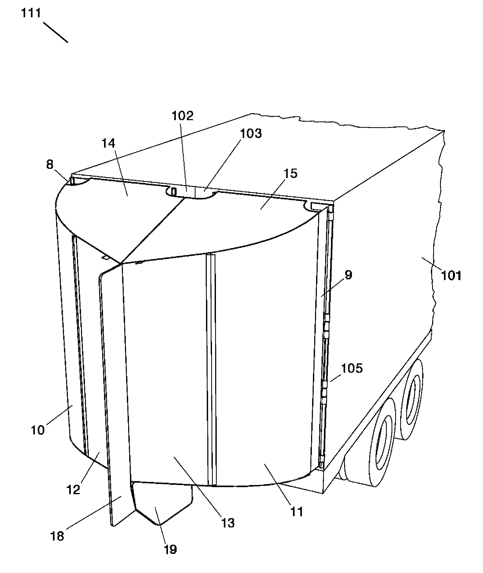
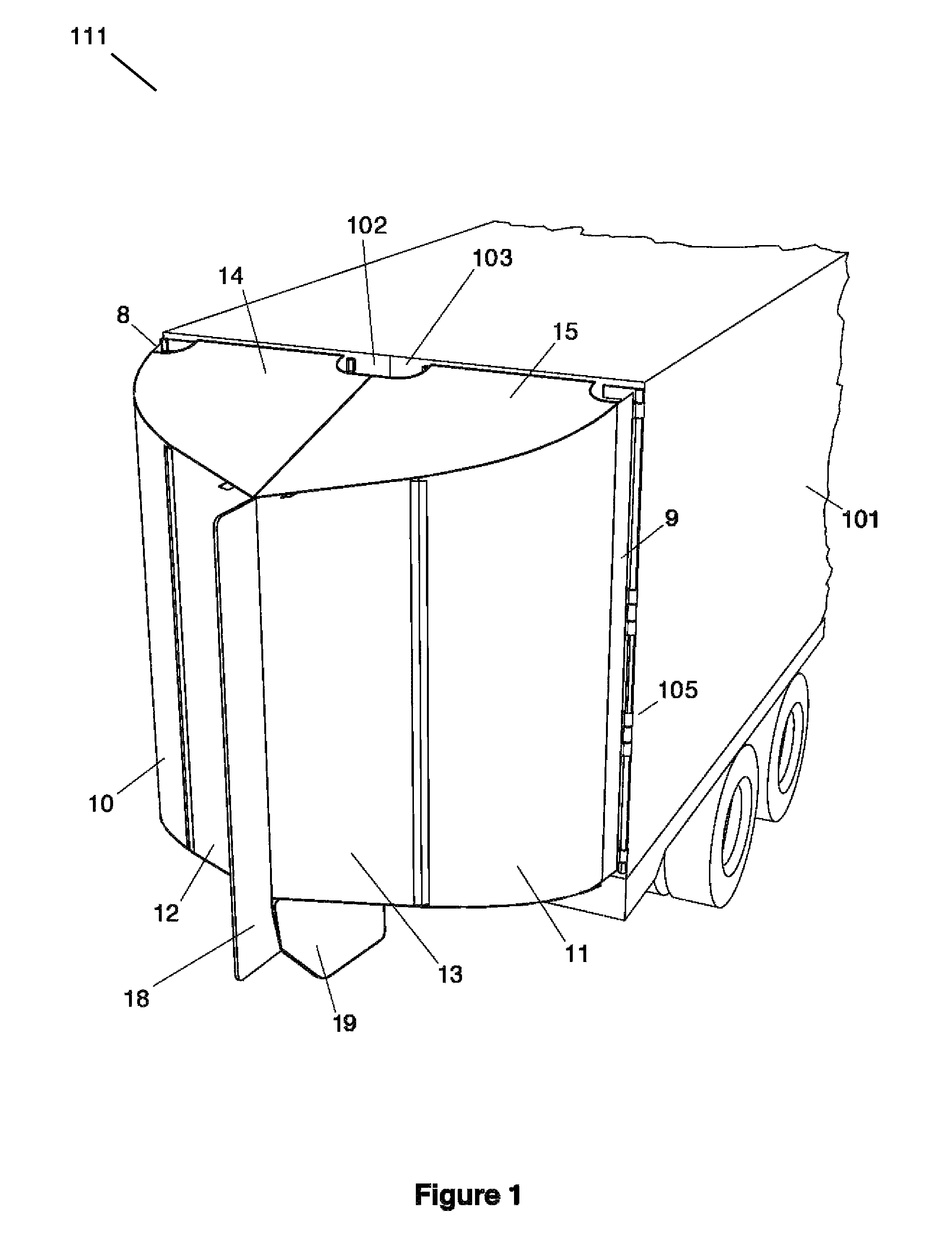
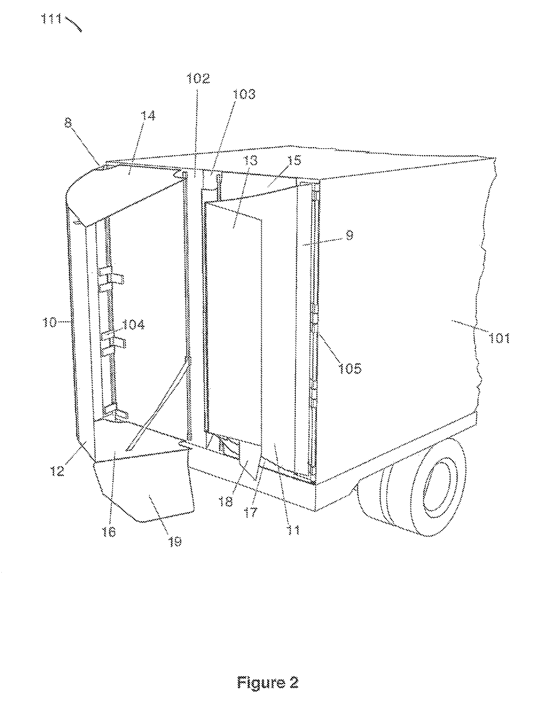
[0024]The tapered contour and teardrop shape of the present invention is formed by sheets of directionally flexible composite material, which are hinged on either side of the trailer via the existing door hinges. These primary panels form a contour ending in a wedge at the rear of the device, a shape established by other sheets hinged to the top and bottom of either door. The vertical sections consist of two distinct sheets, one hinged to the trailer 10&11 and the other to the end of the first section 12&13. They may be folded flat against the door along the axis of these sets of hinges as in FIG. 2. Their segmentation enables length sufficient for the panels to meet a full 4′ behind the trailer, but prevents them from extending beyond the center of the trailer when folded flat against the doors. When deployed, these panels 10, 11, 12&13 form a curved contour, as imposed by separate sheets hinged along the top 14&15 and bottom 16&17 of the trailer as in FIG. 4.

[0025]The primary vert...


PUM


Abstract

The purpose of the device is to minimize drag and turbulence otherwise occurring at the rear of a semi trailer, in order to reduced the consumption of fuel by a semi tractor. This is accomplished using directionally flexible sheets of composite material, which create contours that taper towards a terminating edge to form a teardrop shape, as established by panels attached to the top and bottom of either door. Along the trailing edge of the main body, another vertical panel known as a wake separator maintains separation between confliction columns of air. An additional wake separator attached to the bottom of the device performs a similar function, and will facilitate collapse in the event of a collision.

Description

BACKGROUND OF THE INVENTION[0001]1. Field of the Invention[0002]Of the factors impacting the fuel economy of trucks, tractor-trailers, and other long haul vehicles, it is their aerodynamic efficiency that is, at present, most possible to improve. While tractors are relatively aerodynamic, trailers must assume the form of a box, which, other than those devices intended to intake or inhibit the flow of air, represents the least aerodynamic design. The tractor-trailer is subject to substantial drag as a result of the abrupt termination of the trailer walls at its aft, which creates a partial vacuum and causes turbulent airflow. Ideally speaking, the contour of the trailer and its influenced airflow would taper to a single point or terminating edge, as in a teardrop shape.[0003]In spite of this flaw, the rectangular shape of a box is the only sensible design, as a trailer with an aerodynamic contour will reduce the volume of interior cargo space. It is impossible to compensate for this ...

Claims


Application Information

Patent Timeline
Patent Type & Authority Patents(United States)
IPC IPC(8): B62D35/00
CPCB62D35/001
Inventor KRON, STEVEN TODD
Owner KRON STEVEN TODD
Why Eureka
Try Eureka